Installation for drying organic matter

a technology for installing and drying organic matter, which is applied in the direction of drying machines, furnace types, light and heating equipment, etc., can solve the problems that the putrefaction bacteria cannot increase either, and achieve the effect of lowering the working height and easy implementation

Active Publication Date: 2010-06-03
INOTEC MASCHENENTWICKLUNG & VERTRIEB
View PDF97 Cites 22 Cited by
  • Summary
  • Abstract
  • Description
  • Claims
  • Application Information

AI Technical Summary

Benefits of technology

[0025]By means of the adjustable motors, the rotational speed of the mixing blades can be matched to the respective material to be mixed, for example coarse or fine. The fact that the housing can be displaced in the vertical direction with respect to the subframe means that any desired working height can be set. This is advantageous during manual loading or during automatic loading from another machine. The working height can be lowered to such an extent that automatic loading from relatively low processing machines is also possible or the material to be mixed can be put in by hand. In the raised position, it is possible to push a transport wagon in a straightforward manner under the side of the mixer on which the outlet of the emptying opening is provided. By means of an appropriate direction of rotation of the outer blades, because of the turning the material to be mixed is pushed out through the open emptying opening and falls into a conveying installation with conveyor belt and/or screw conveyor, into a transport wagon or into a sack, bag, carton or another container which can be closed and/or evacuated and/or welded.
[0026]The closure element for closing the emptying opening in a simple configuration can be a pivotable flap or a slide with a rubber seal, which is fixed to the outer side of an end wall such that it can be pivoted about an upper horizontal pivot axis. The emptying opening is located in the end. For the purpose of actuation, it is expedient to use a toggle lever mechanism which, as is known, comprises a first lever which has to be fi

Problems solved by technology

As a result of the possibility of continuous loading and of the process sequence within one da

Method used


Image

  • Installation for drying organic matter
  • Installation for drying organic matter
  • Installation for drying organic matter

Examples


Embodiment Construction

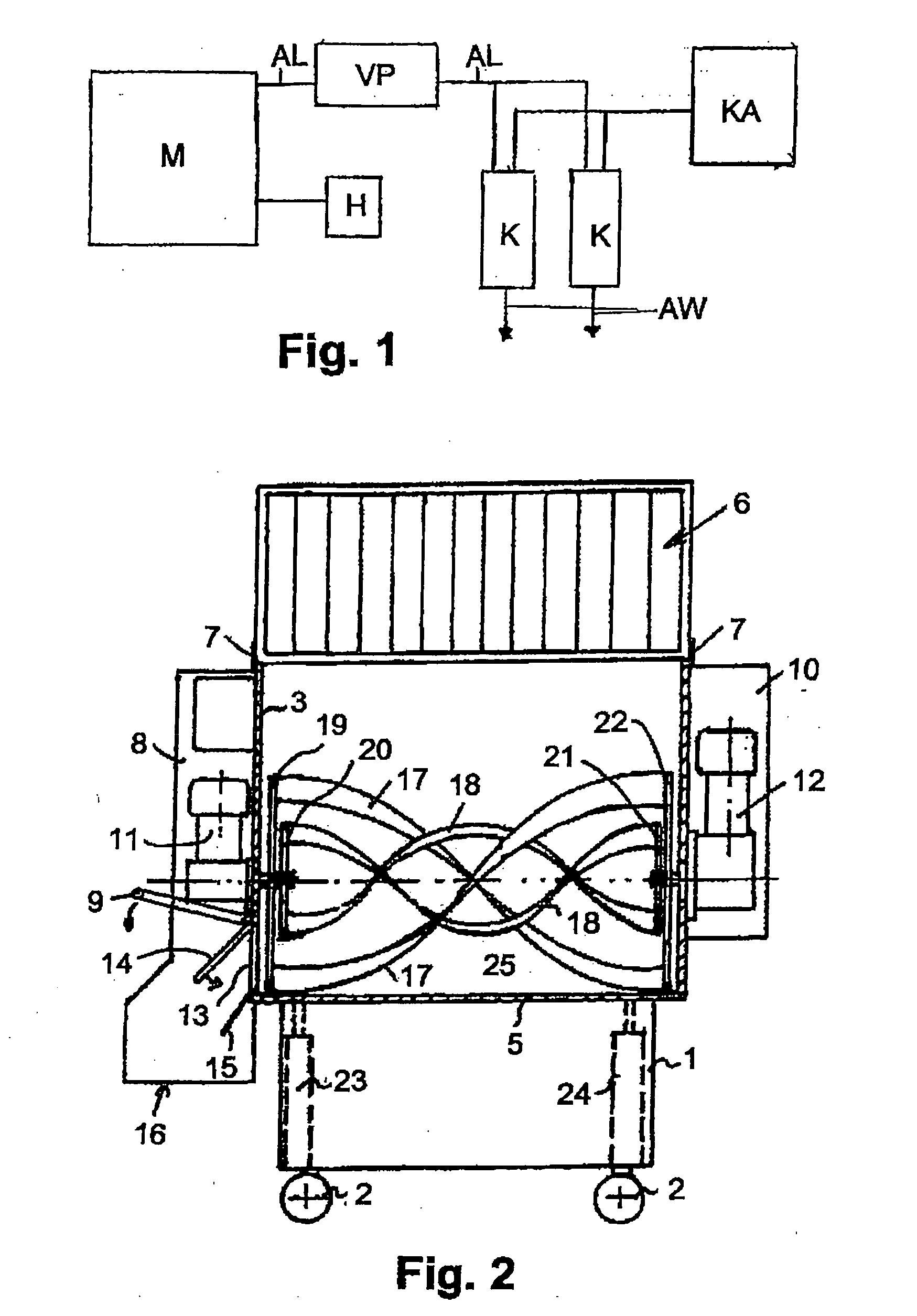
[0034]FIG. 1 indicates an installation according to the invention schematically in the form of a block diagram. The mixer M is constructed as a vacuum mixer. It can be loaded at the top, for example, and, as described by using the further figures, is sealed off in an airtight manner by a hood and is connected to a waste air line AL, which is connected to a vacuum pump VP. Furthermore, a heating device H is also provided, with which the material to be mixed put in is heated, for example to about 80° C. By using the vacuum pump VP, a vacuum between 100 and 2 mbar, for example, is generated in the mixer housing. The extracted air is fed via the waste air line AL to the two condensers K, in which the vapor contained is condensed to form wastewater AW. This wastewater AW can then be fed directly to a sewer connection or collected in a condensate container and then fed to a wastewater sewer under control with the aid of valve technology. The condensers are commercially available condenser...


PUM


Abstract

An installation for drying organic matter, especially kitchen and food wastes or other biological matter, including matter that contains packaging residues, napkins, straws or the like. The installation comprises the following components: (a) a vacuum mixer (M) having a closable charging opening for introducing the organic matter and a closable discharge opening, disposed at the bottom or laterally towards the bottom, for the dried matter, (b) at least one vacuum pump (VP) for evacuating the air in the mixer to generate the vacuum, the pump being connected to at least one evacuation tube mounted above the maximum filling level in the housing of the mixer (M), (c) a heater (H) for heating the organic matter, (d) at least one condenser (K), connected to the air evacuation duct (AL) of the vacuum pump (VP) and having a cooling unit (KA) connected thereto to condense the evacuated air, and (e) a discharge duct (AW) for the condensate obtained from the evacuated air by cooling in the condenser (K).

Description

BACKGROUND OF THE INVENTION[0001]The invention relates to an installation for drying organic matter, in particular kitchen and food wastes or other biological matter, including those which contain packaging residues, napkins, straws or the like, having the following components:[0002]a) a vacuum mixer having at least one mixing blade in a housing and having a closable filling opening for introducing the organic matter and a closable emptying opening on the underside or laterally toward the underside for the dried matter,[0003]b) at least one vacuum pump, connected to at least one extraction connector fitted in the housing of the mixer above the maximum filling height, in order to extract the air in the mixer to produce the vacuum,[0004]c) a heating device for heating the organic matter,[0005]d) at least one condenser, connected to the waste air line of the vacuum pump, and having a cooling unit connected thereto for condensing the extracted air, and[0006]e) a drain line for the conde...

Claims


Application Information

Patent Timeline
IPC IPC(8): F26B3/347F26B13/30F26B21/06F26B19/00
CPCB01F7/088Y02E50/30B01F15/00785C02F11/12C10L5/44C10L5/46F23G5/04F23G2201/80F23G2900/50206F23K2201/1006F23K2201/20F26B1/005F26B5/048F26B11/16F26B25/006Y02E50/10B01F13/06C02F11/131B01F27/1142B01F27/726B01F33/70B01F35/451B29C48/00
Inventor KRUGER, GUNTER
Owner INOTEC MASCHENENTWICKLUNG & VERTRIEB
Why Eureka
Try Eureka