
Electrostatic charging and collection

a technology of electrostatic charging and collection, applied in the direction of instruments, particle separator tube details, separation processes, etc., can solve the problems of substantial drift and collection of particulates, and achieve the effects of reducing the deposition of particulates, reducing the amount of particulates, and high charging of particulates

Inactive Publication Date: 2010-06-03
EXCELLIMS CORP
View PDF3 Cites 10 Cited by
  • Summary
  • Abstract
  • Description
  • Claims
  • Application Information

AI Technical Summary

Benefits of technology

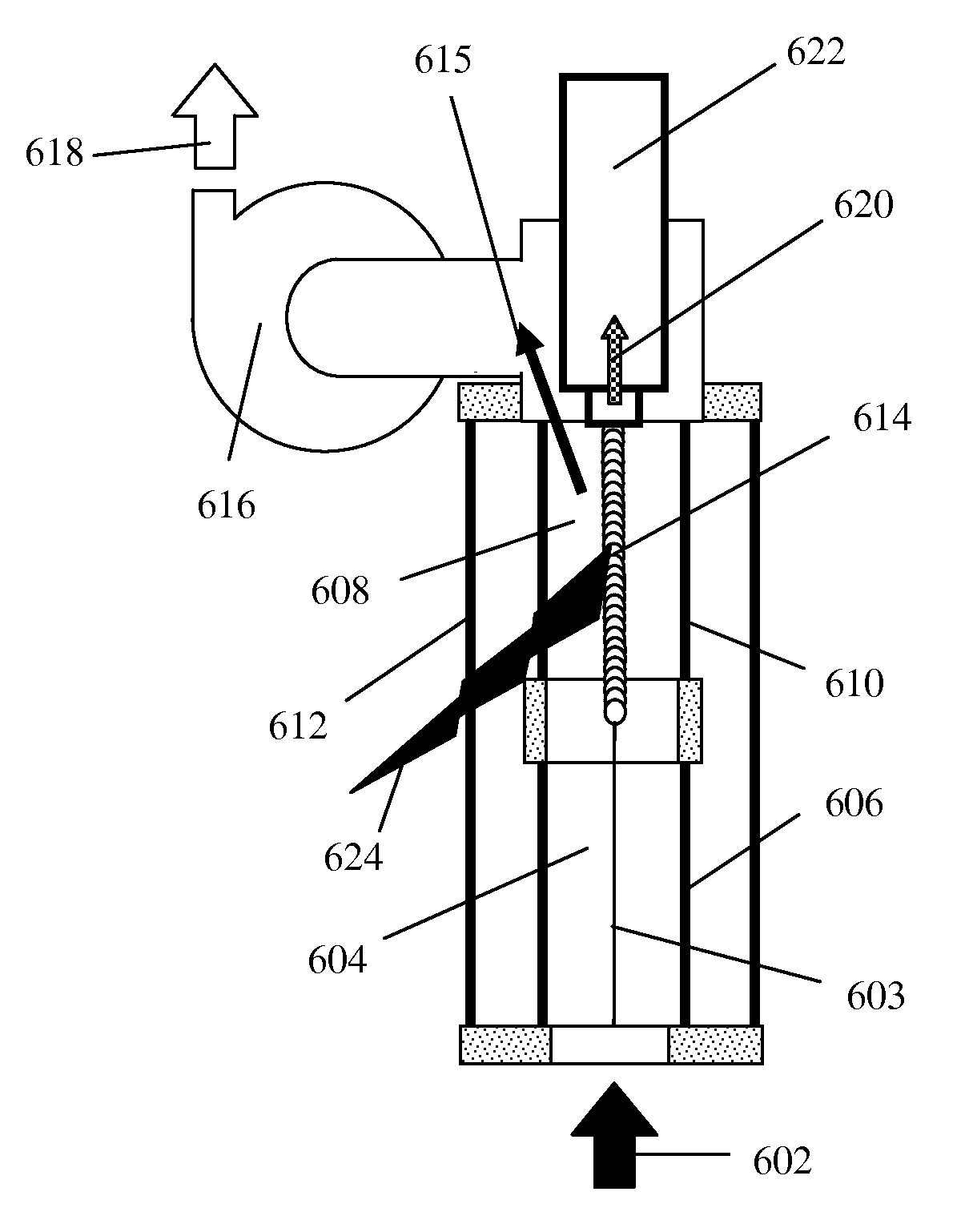
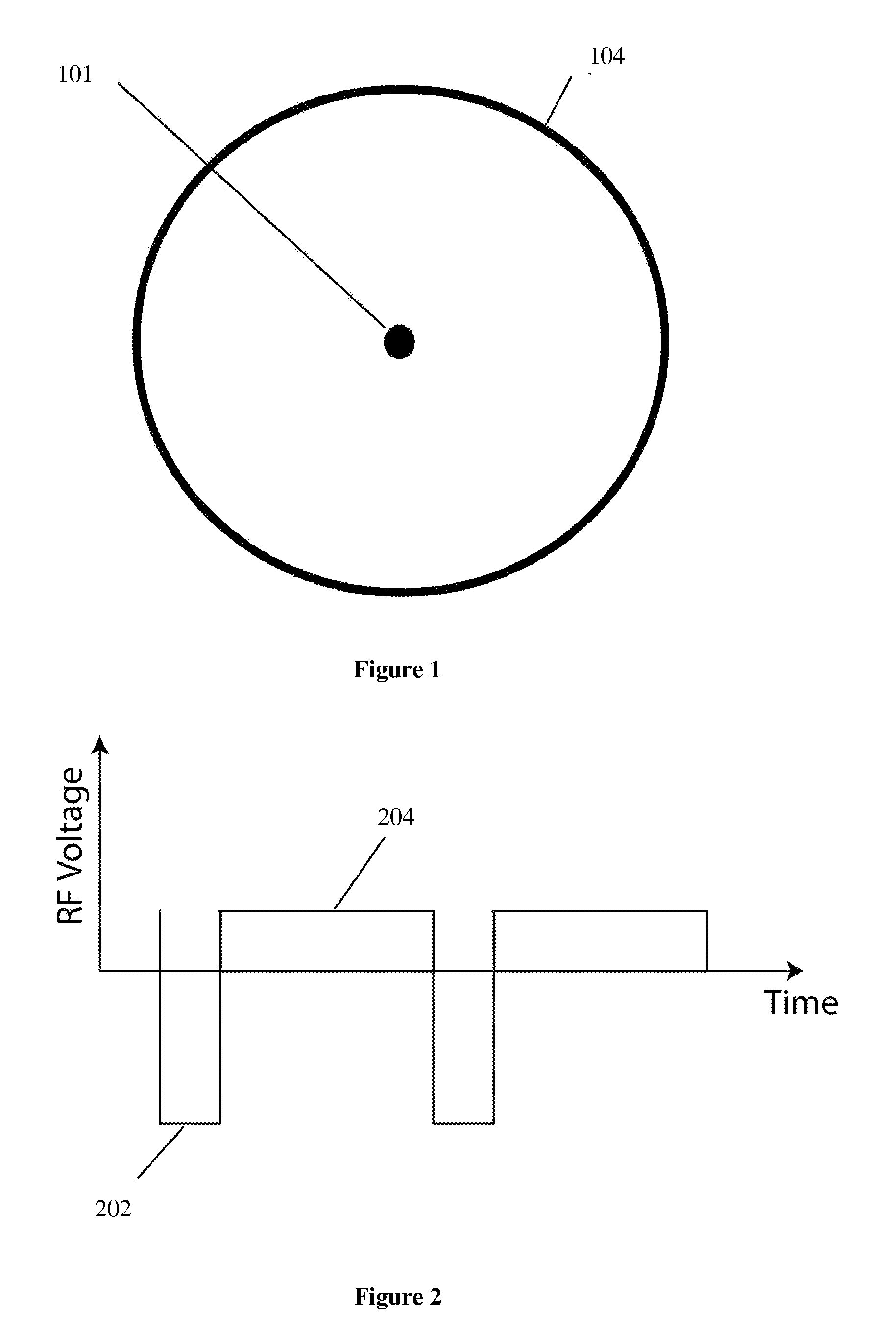
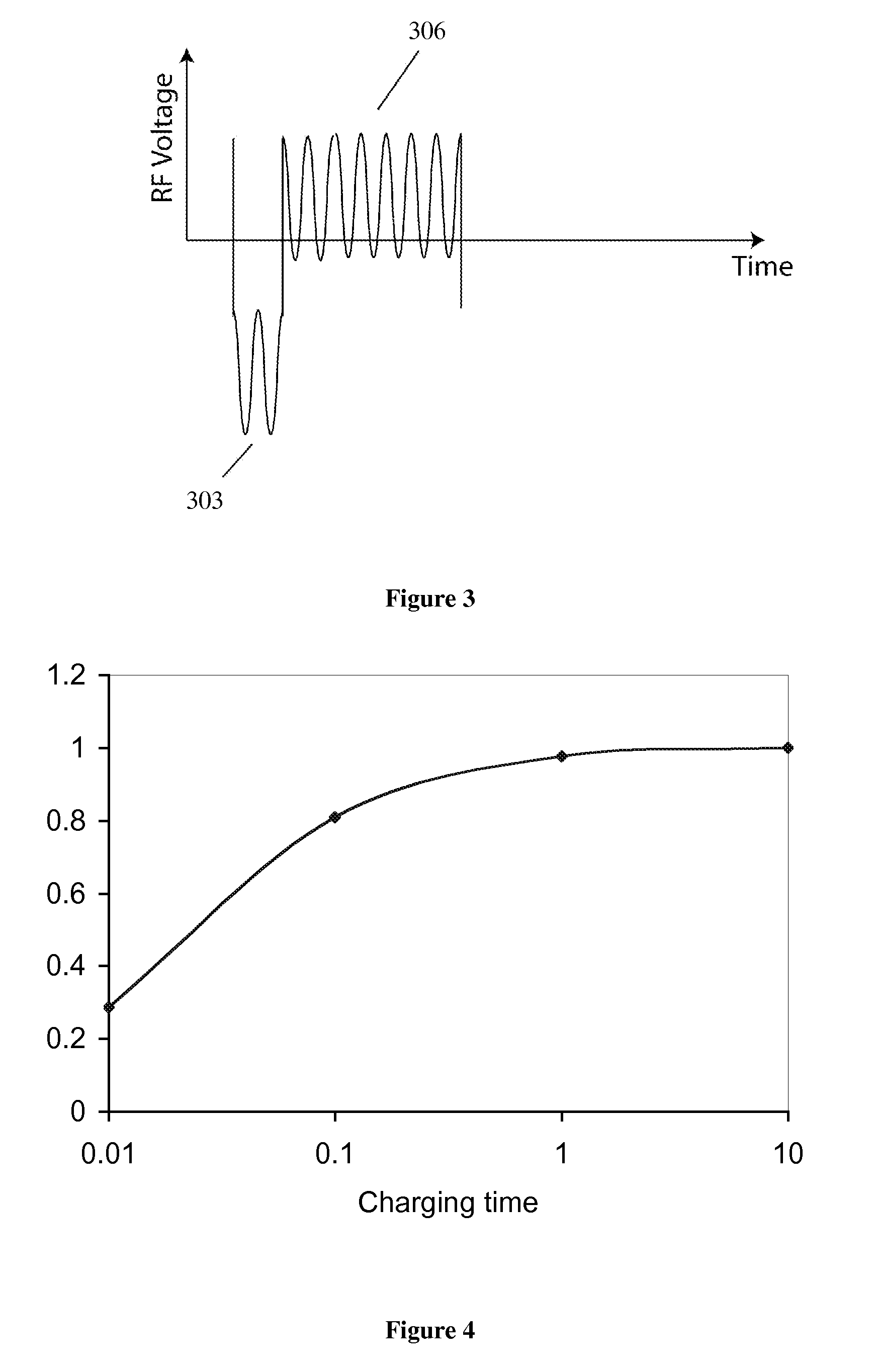
[0006]One aspect of the present invention is a particulate charging method comprising the following steps: charging a particulate gaseous stream, applying an AC waveform, inducing ions from an ionization source during a fraction of the AC waveform of a given polarity, and not inducing ions from the ionization source during a fraction of the AC waveform of a opposite polarity. A frequency can be applied to the AC waveform such that the particulates will not experience a substantial electric drift during each fraction of the AC waveform. The duty cycle of the fraction of the AC waveform that induces ions from an ionization source to that of the fraction of the AC waveform of opposite polarity and without ion scan being adjusted to substantially decrease the deposition of the particulates on either electrode in a charging section. Another aspect of the present invention, provides a means of high charging of the particulates while minimizing their collection in the charging stage. During the particulate charging method, the collection of particles is minimized during charging. Yet another aspect of the present invention provides a means for efficiently collecting the particulates in a second stage for sampling in a compact electrode. The particulate charging method may also include collecting particles. In addition, the collected particles can be heated in order to vaporize the particles. Also, theses particles and / or vapors can be analyzed.

Problems solved by technology

However, there is substantial drift and collection of the particulates in the charging stage.

Method used


Image

  • Electrostatic charging and collection
  • Electrostatic charging and collection
  • Electrostatic charging and collection

Examples


Embodiment Construction

[0017]As used herein, the term “analytical instrument” generally refers to ion mobility based spectrometer, MS, other spectroscopy and spectrometry and any other instruments that have the same or similar functions.

[0018]Unless otherwise specified in this document the term “ion mobility based spectrometer” is intended to mean any device that separates ions based on their ion mobilities or mobility differences under the same or different physical and chemical conditions and detecting ions after the separation process. Many embodiments herein use the time of flight type IMS, although many features of other kinds of IMS, such as differential mobility spectrometer and field asymmetric ion mobility spectrometer are included. Unless otherwise specified, the term ion mobility spectrometer or IMS is used interchangeable with the term ion mobility based spectrometer defined above.

[0019]Unless otherwise specified in this document the term “mass spectrometer” or MS is intended to mean any devic...


PUM


Abstract

The present invention describes directly using particles collected with an electrostatic precipitator for the detection of explosives and other compounds of interest. The method and apparatus of analyzing particles involves directly measuring particles on the collection electrodes or thermally desorbing them into an ion mobility spectrometer and / or other analytical instruments. One aspect of the present invention is a particulate charging method. Another aspect of the present invention provides a means of high charging of the particulates while minimizing their collection in the charging stage. The present invention also provides a means for efficiently collecting the particulates in a second stage for sampling in a compact electrode.

Description

CROSS-REFERENCE TO RELATED APPLICATIONS[0001]The present application is a continuation in part of U.S. patent application Ser. No. 11 / 736,233, filed on Apr. 17, 2007, and claims the benefit of and priority to corresponding U.S. Provisional Patent Application Ser. No. 61 / 148,996, filed Feb. 1, 2009 respectively; the entire content of the application is herein incorporated by reference.BACKGROUND OF THE INVENTION[0002]Electrostatic precipitators have been used in industrial settings for particulate control and environmental sampling. One way to differentiate electrostatic precipitators is whether they use single or two stage precipitators. In a single stage precipitator, both the charging of the particulates and their removal occurs in the same region of the electrostatic precipitator. In the two-stage configuration, charging of the particulates occurs at a different location from their removal.[0003]Charging of the particulates is a function of: the ambient electric field, the backgr...

Claims


Application Information

Patent Timeline
Patent Type & Authority Applications(United States)
IPC IPC(8): B03C3/011H01J49/02
CPCG01N1/14G01T1/00G01N2001/028G01N2001/022
Inventor BROMBERG, LESLIEWU, CHINGOSGOOD, MARK A.
Owner EXCELLIMS CORP
Learn More