Plasma jet ignition plug ignition control

Inactive Publication Date: 2010-06-03
NGK SPARK PLUG CO LTD
View PDF12 Cites 29 Cited by
  • Summary
  • Abstract
  • Description
  • Claims
  • Application Information

AI Technical Summary

Benefits of technology

[0028]The control system of the eleventh aspect can adjust the quantity of electric power applied to the plasm

Problems solved by technology

However, since the plasma-jet spark plug requires the supply of energy in a large quantity in order to produce plasma, the plasma-jet spark plug is inferior in the durabilit

Method used


Image

  • Plasma jet ignition plug ignition control
  • Plasma jet ignition plug ignition control
  • Plasma jet ignition plug ignition control

Examples


Embodiment Construction

[0053]An embodiment or embodiments of the present invention is explained below in the following order, with reference to the drawings.

[0054]A. Outline of configuration of control system

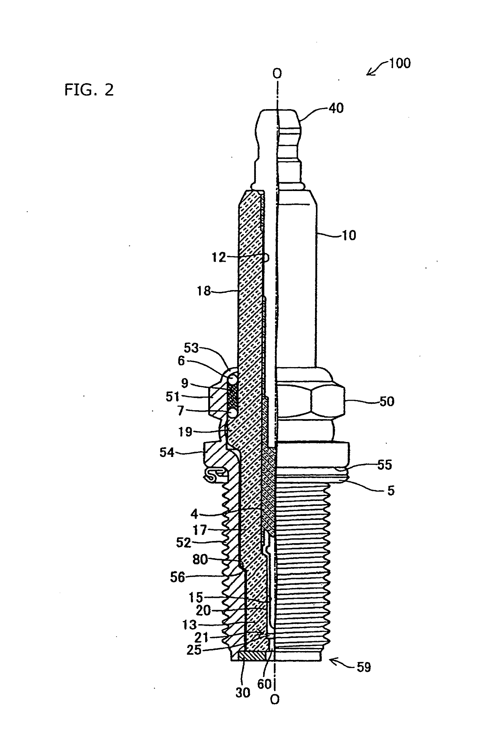
[0055]B. Construction of plasma-jet spark plug

[0056]C. Operation control of internal combustion engine

[0057]D. Various make-ups of ignition device

[0058]E. Practical examples

[0059]A. Outline of Configuration of Control System

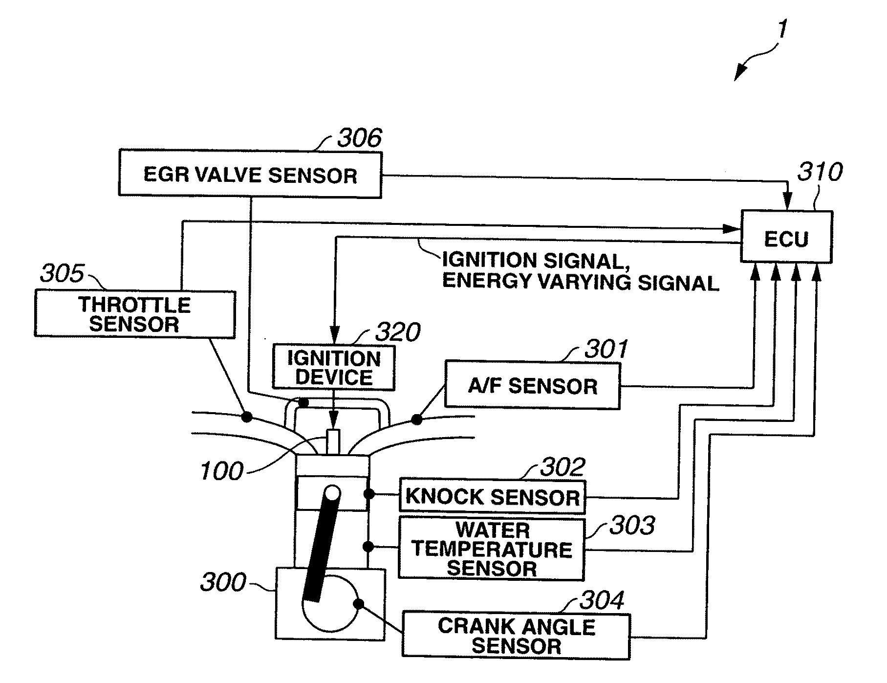
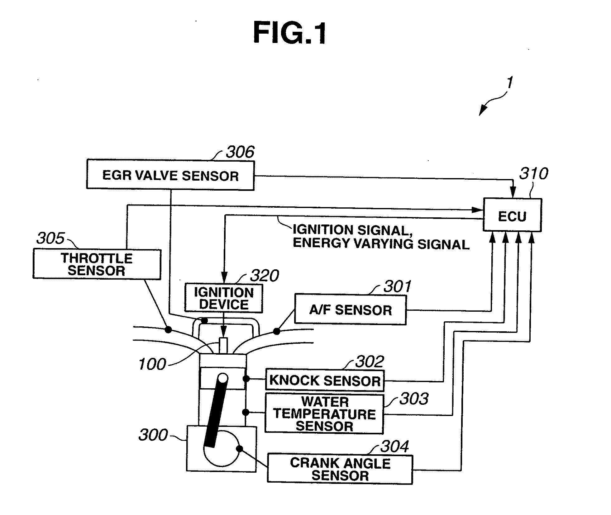
[0060]FIG. 1 is a view for illustrating a control system for controlling the ignition of a plasma-jet spark plug in outline. The control system 1 shown in FIG. 1 includes an internal combustion engine 300 provided with a plasma-jet spark plug 100, an ignition device 320 to perform an ignition of the plasma-jet spark plug 100, various sensors to sense one or more operating conditions of internal combustion engine 300, and an ECU (Engine Control Unit) 310 connected with these sensors.

[0061]Internal combustion engine 300 is an ordinary four stroke gasoline engine. Internal combustion ...


PUM


Abstract

A control system for controlling the ignition of a plasma-jet spark plug provided in an internal combustion engine senses an operating condition of the internal combustion engine, and determines an ignition mode of the plasma-jet spark plug in accordance with the sensed operating condition. The control system performs an ignition control of breaking down the insulation across a spark discharge gap by applying a first electric power to the plasma-jet spark plug, and producing plasma in the vicinity of the spark discharge gap by applying a second electric power to the spark discharge gap in a state of dielectric breakdown. The control system performs this ignition control according to the ignition mode determined as mentioned above.

Description

TECHNICAL FIELD[0001]The present invention relates to technique of controlling a plasma-jet spark plug arranged to produce plasma to ignite a mixture gas, for an internal combustion engine.BACKGROUND ART[0002]A spark plug for igniting a mixture gas with a spark discharge is used conventionally for an engine or an internal combustion engine for a motor vehicle. Recently, there is a demand for higher output and lower fuel consumption of an internal combustion engine. Accordingly, development is in progress for a plasma-jet spark plug capable of providing faster propagation of combustion, and igniting a lean mixture gas for higher ignition limit air fuel ratio (cf. patent document 1, for example).[0003]Patent document 1: JP 2007-287666 A[0004]The plasma-jet spark plug has a structure including a discharge space (cavity) of a small volume formed by an insulator, such as ceramic insulator, surrounding a spark discharge gap between a center electrode and a ground electrode. In one example...

Claims


Application Information

Patent Timeline
IPC IPC(8): F02P5/00F02P7/02
CPCH01T13/50F02P9/007
Inventor SATO, YOSHIKUNINAKANO, DAISUKEYAMADA, YUICHINAKAMURA, TORU
Owner NGK SPARK PLUG CO LTD
Why Eureka
Try Eureka