Method and apparatus for producing amorphous ribbon

Active Publication Date: 2010-06-03
NIPPON STEEL CORP
View PDF2 Cites 10 Cited by
  • Summary
  • Abstract
  • Description
  • Claims
  • Application Information

AI Technical Summary

Benefits of technology

[0012]The problem sought to be solved in the achievement of the present invention was to enable the circumferential surface of a cooling roll used to produce amorphous ribbon to be polished online in the lateral direction of the cooling roll during the production so

Problems solved by technology

This study revealed that (i) when the ribbon on the cooling roll is contracted by solidification of the molten alloy, solidified portions invading minute recesses in the cooling roll surface scrape and produce scratches on the cooling roll surface, (ii) the contraction of t

Method used


Image

  • Method and apparatus for producing amorphous ribbon
  • Method and apparatus for producing amorphous ribbon
  • Method and apparatus for producing amorphous ribbon

Examples


examples

First Set of Examples

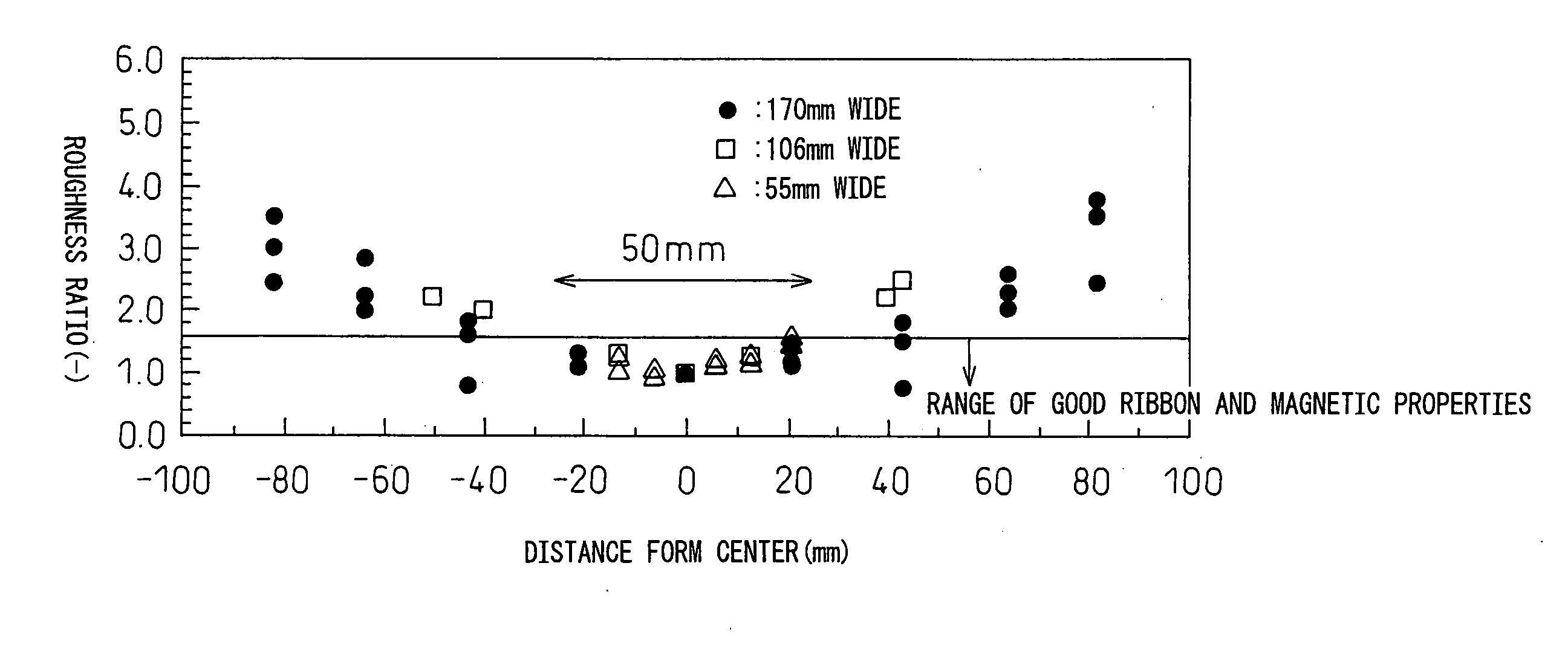
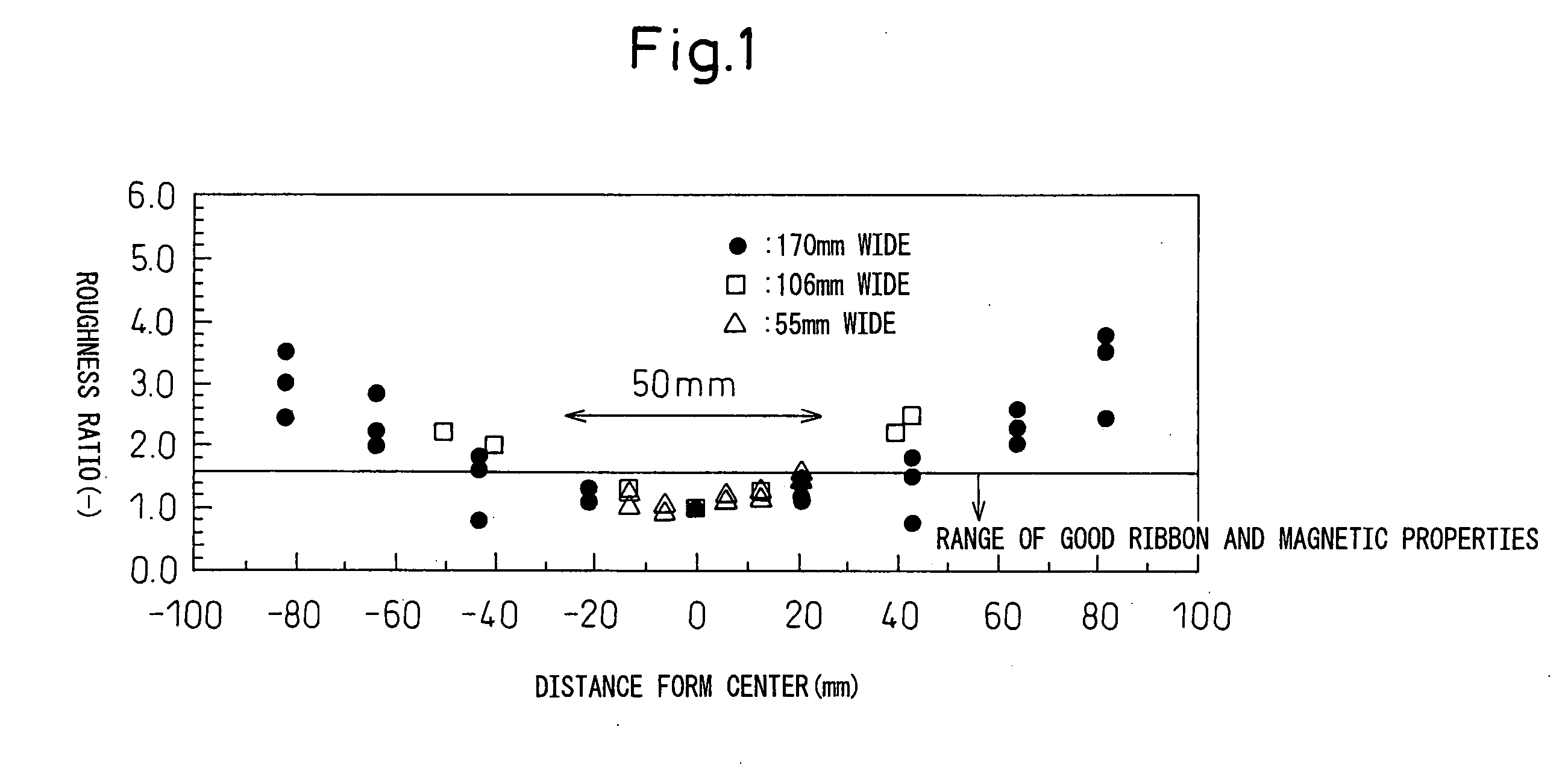
[0099]Using a single-roll apparatus configured as shown in FIG. 3, molten Fe alloy containing, in at %, Fe: 80.5%, Si: 6.5%, B: 12% and C: 1% was jetted from a 170 mm×0.85 mm rectangular slit-shaped nozzle onto the surface of a cooling roll measuring 1,198 mm in diameter and 250 mm width to produce an Fe amorphous ribbon measuring 170 mm in width and about 30 μm in thickness. The peripheral speed of the cooling roll during production was set at 21 m / s. The production conditions are shown in Table 1.

TABLE 1Production conditionsProductionCorePolishingtimeloss (W / kg)Member(min)MiddleEdgeInvention 1One stage,250.0820.098NotsubdividedInvention 2Two stages,230.0910.087SubdividedInvention 3Two stages,230.0830.089SubdividedInvention 4Two stage,260.0810.079NotsubdividedComparativeOne stage240.0920.152Example 1ComparativeOne stages270.1060.162Example 2

[0100]In Invention Example 1, the polishing member was a resin brush roll configured as shown in FIG. 4(a) that measured 1...


PUM

PropertyMeasurementUnit
Fractionaaaaaaaaaa
Lengthaaaaaaaaaa
Surface propertiesaaaaaaaaaa

Abstract

A method and apparatus are provided for producing an amorphous ribbon by ejecting and rapidly solidifying molten alloy on a circumferential surface of a rapidly rotating cooling roll, wherein the cooling roll is polished online during amorphous ribbon production. When the circumferential surface of the cooling roll after peeling off the ribbon is polished using a polishing member, the circumferential surface of the cooling roll is polished continuously or intermittently across its lateral direction while differentiating the polishing mode in accordance with the surface properties.

Description

FIELD OF THE INVENTION[0001]This invention relates to a method and an apparatus for producing an amorphous ribbon by ejecting molten alloy onto a cooling roll to be rapidly cooled and solidified, and particularly to such a method and an apparatus that polish the cooling roll online during amorphous ribbon production.DESCRIPTION OF THE RELATED ART[0002]The production method generally used to produce amorphous ribbon is the single roll method in which the molten alloy is usually ejected onto the circumferential surface of a cooling roll rotating at high speed to cool and solidify the molten alloy rapidly by the heat removing action of the cooling roll.[0003]In the single roll method, the molten alloy must be rapidly cooled at a cooling rate of around 104 to 105° C. / s. A cooling roll made of copper alloy or other metal material of large thermal conductivity is therefore ordinarily used as a cooling roll that can rapidly remove heat from the molten alloy.[0004]In industrial production, ...

Claims


Application Information

Patent Timeline
IPC IPC(8): B22D27/04B22D23/00B22D25/06
CPCB22D11/0674B22D11/0611
Inventor OZAKI, SHIGEKATSUIMAI, TAKESHI
Owner NIPPON STEEL CORP
Why Eureka
Try Eureka