
Substrate having metal post and method of manufacturing the same

Inactive Publication Date: 2010-06-03
SAMSUNG ELECTRO MECHANICS CO LTD
View PDF4 Cites 25 Cited by
  • Summary
  • Abstract
  • Description
  • Claims
  • Application Information

AI Technical Summary

Benefits of technology

[0017]Accordingly, the present invention has been made keeping in mind the above problems occurring in the prior art, and the present invention provides a substrate having a metal post and a method of manufacturing the same, which are configured to prevent oxidation and corrosion of the metal post.
[0018]Furthermore, the present invention provides a substrate having a metal post and a method of manufacturing the same, which is configured to prevent the occurrence of recesses or pits on a solder bump formed on the metal post.
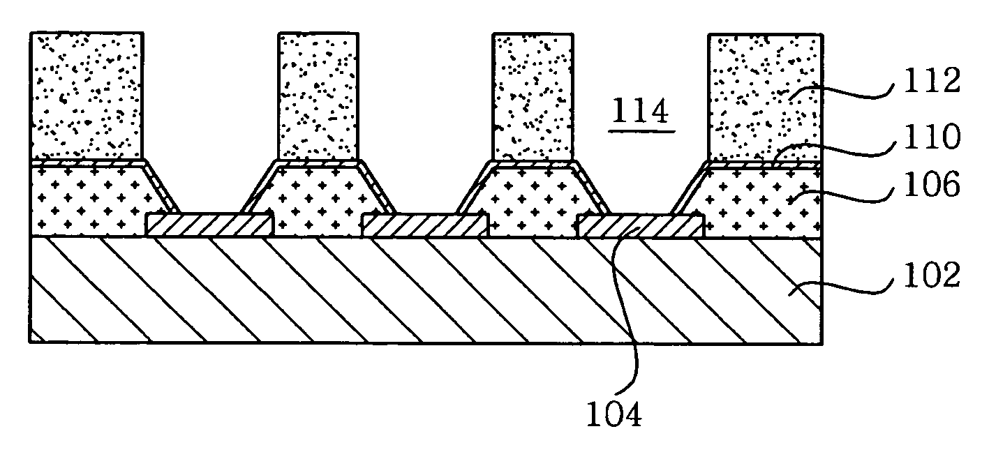
[0029]In another aspect, the present invention provides a method of manufacturing a substrate, including: (A) preparing a base substrate having a connecting pad thereon, forming a solder resist layer on the base substrate, the solder resist layer having a first opening through which the connecting pad is exposed, and forming a seed layer on the solder resist layer including the first opening; (B) applying photosensitive resist on the solder resist layer including the first opening, and forming a second opening in the photosensitive resist such that the connecting pad is exposed through the second opening; (C) forming a metal post in the second opening to be connected to the connecting pad such that the second opening is partially filled with the metal post; (D) applying solder paste on the metal post in the second opening, subjecting the solder paste to a first reflow process to provide an upper round solder bump part, and removing the photosensitive resist and the seed layer; and (E) subjecting the round solder bump to a second reflow process to provide on a lateral surface of the metal post a the solder bump film for preventing oxidation.

Problems solved by technology

In the case of the wire bonding process, electronic components must be connected to a PCB using a wire, thus increasing a size of the resulting module and requiring additional processes.
Furthermore, the wire bonding process has a limit concerning the realization of a finely pitched circuit pattern.
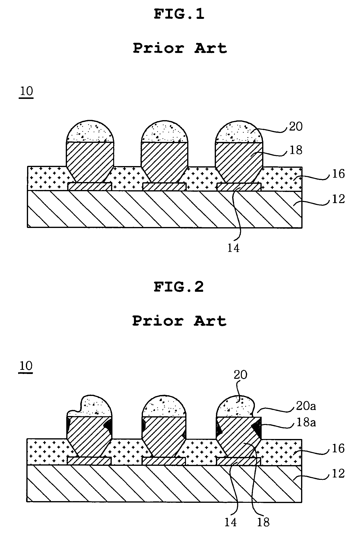
Unfortunately, the conventional PCB 10 having metal posts has the disadvantages below.
In addition, the related art has another problem in that the solder bumps 20 are dissolved by chemicals used in the process.
This hinders provision of solder bumps 20 having even heights, thus deteriorating the reliability of the connection.
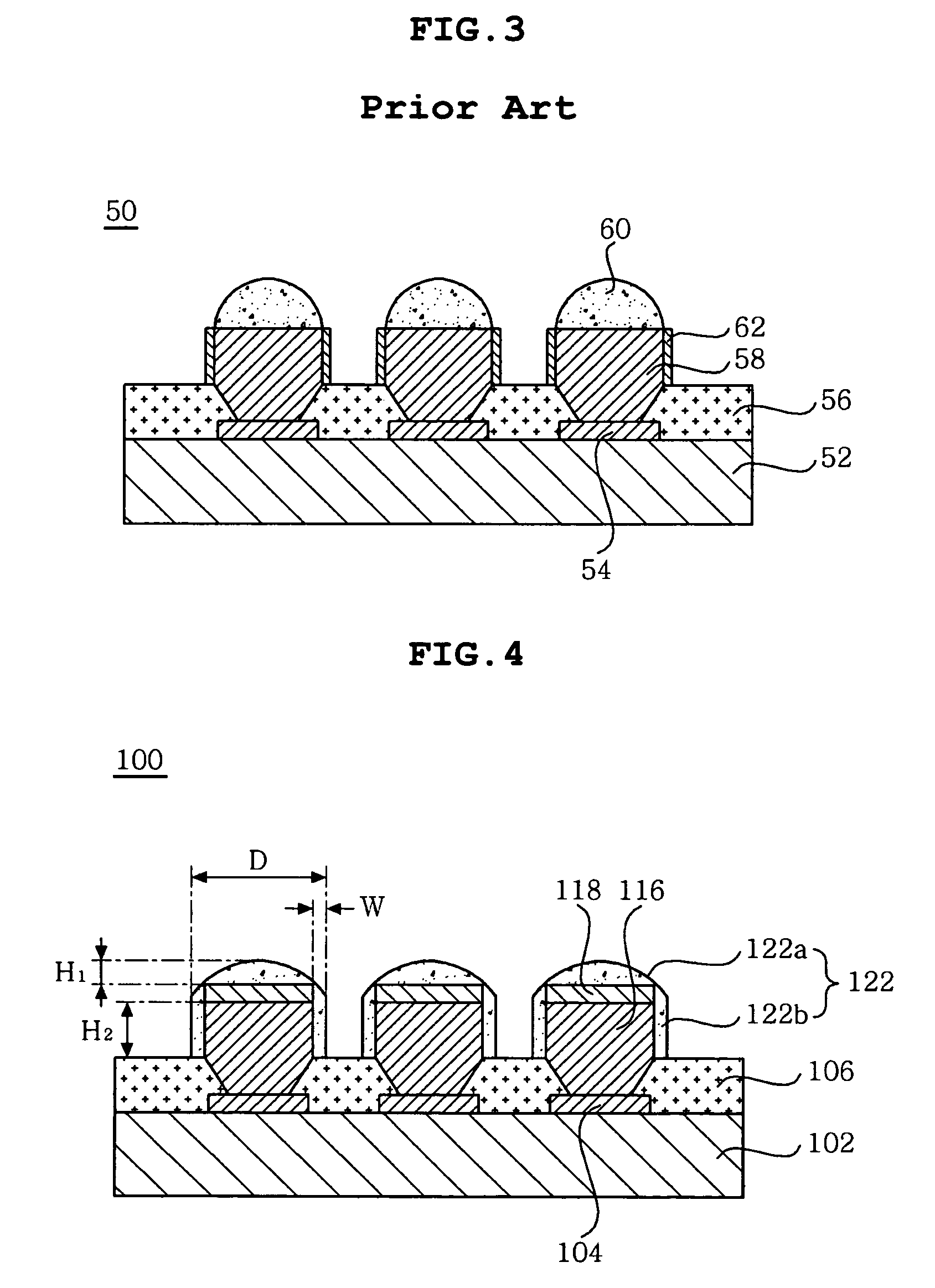
Nevertheless, the second conventional PCB 50 having metal posts also has disadvantages in that it requires additional materials and processing for the formation of the oxidation-inhibiting caps 62 and the solder bumps 60 formed on the metal posts 58 still contain recesses formed thereon.

Method used


Image

  • Substrate having metal post and method of manufacturing the same
  • Substrate having metal post and method of manufacturing the same
  • Substrate having metal post and method of manufacturing the same

Examples


Embodiment Construction

[0047]Various objects, advantages and features of the invention will become apparent from the following description of embodiments with reference to the accompanying drawings.

[0048]The terms and words used in the present specification and claims should not be interpreted as being limited to typical meanings or dictionary definitions, but should be interpreted as having meanings and concepts relevant to the technical scope of the present invention based on the rule according to which an inventor can appropriately define the concept of the term to best describe the method he or she knows for carrying out the invention.

[0049]Concerning the designations of reference numerals, it should be noted that the same reference numerals are used throughout the different drawings to designate the same or similar components. Also, in the description of the present invention, when it is considered that the detailed description of a related prior art may obscure the gist of the present invention, suc...


PUM

PropertyMeasurementUnit
Fractionaaaaaaaaaa
Fractionaaaaaaaaaa
Thicknessaaaaaaaaaa

Abstract

The invention relates to a substrate having a metal post and a method of manufacturing the same, in which a round solder bump part formed on a metal post melts and flows down along a lateral surface of the metal post by being subjected twice to a reflow process, thus forming a solder bump film for preventing oxidation and corrosion of the metal post.

Description

CROSS REFERENCE TO RELATED APPLICATION[0001]This application claims the benefit of Korean Patent Application No. 10-2008-0119805, filed Nov. 28, 2008, entitled “A Substrate having a Metal Post and a Fabricating Method of the Same”, which is hereby incorporated by reference in its entirety into this application.BACKGROUND OF THE INVENTION[0002]1. Field of the Invention[0003]The present invention relates to a substrate having a metal post and a method of manufacturing the same, and more particularly to a substrate having a metal post and a method of manufacturing the same, which realizes a novel configuration capable of preventing oxidation and corrosion while using a simple process.[0004]2. Description of the Related Art With the recent advancement of the electronics industry, there is a demand for increasing performance and functionality of electronic components and reducing the size thereof. Accordingly, high integration, slimness and fine circuit patterning are also required on a ...

Claims


Application Information

Patent Timeline
IPC IPC(8): H05K1/11B05D5/12
CPCH01L23/49816H01L23/49894H01L2924/0002H01L2224/0401H01L2924/01327H01L2224/16H01L2924/01046H01L2924/01078H01L2924/01079H05K3/243H05K3/3484H05K3/4007H05K2201/0367H05K2203/043H05K2203/054H05K2203/0568H05K2203/0571H05K2203/1476H01L2224/05567H01L2224/13022H01L2924/01019H01L2924/00H01L2224/05552H05K3/3485H05K1/02H05K3/40
Inventor LEE, DONG GYUCHOI, JIN WONKO, YOUNG GWANMUN, SEON JAECHUNG, TAE JOON
Owner SAMSUNG ELECTRO MECHANICS CO LTD
Learn More