
Solid state lighting device with improved heatsink

a technology of solid-state lighting and heatsink, which is applied in the direction of semiconductor devices for light sources, lighting and heating apparatus, transportation and packaging, etc., can solve the problem of generating significant amounts of heat that must be dissipated

Active Publication Date: 2010-06-03
IDEAL IND LIGHTING LLC
View PDF10 Cites 95 Cited by
  • Summary
  • Abstract
  • Description
  • Claims
  • Application Information

AI Technical Summary

Benefits of technology

[0017]Other aspects, features and embodiments of the invention will be more fully apparent from the ensuing disclosure and appended claims.

Problems solved by technology

High power solid state emitters can draw large currents, thereby generating significant amounts of heat that must be dissipated.

Method used


Image

  • Solid state lighting device with improved heatsink
  • Solid state lighting device with improved heatsink
  • Solid state lighting device with improved heatsink

Examples


Embodiment Construction

[0032]The present invention now will be described more fully hereinafter with reference to the accompanying drawings, in which embodiments of the invention are shown. The present invention may, however, be embodied in many different forms and should not be construed as limited to the specific embodiments set forth herein. Rather, these embodiments are provided to convey the scope of the invention to those skilled in the art. In the drawings, the size and relative sizes of layers and regions may be exaggerated for clarity.

[0033]It will be understood that when an element such as a layer, region or substrate is referred to as being “on” or extending “onto” another element, it can be directly on or extend directly onto the other element or intervening elements may also be present. In contrast, when an element is referred to as being “directly on” or extending “directly onto” another element, no intervening elements are present. It will also be understood that when an element is referred...


PUM


Abstract

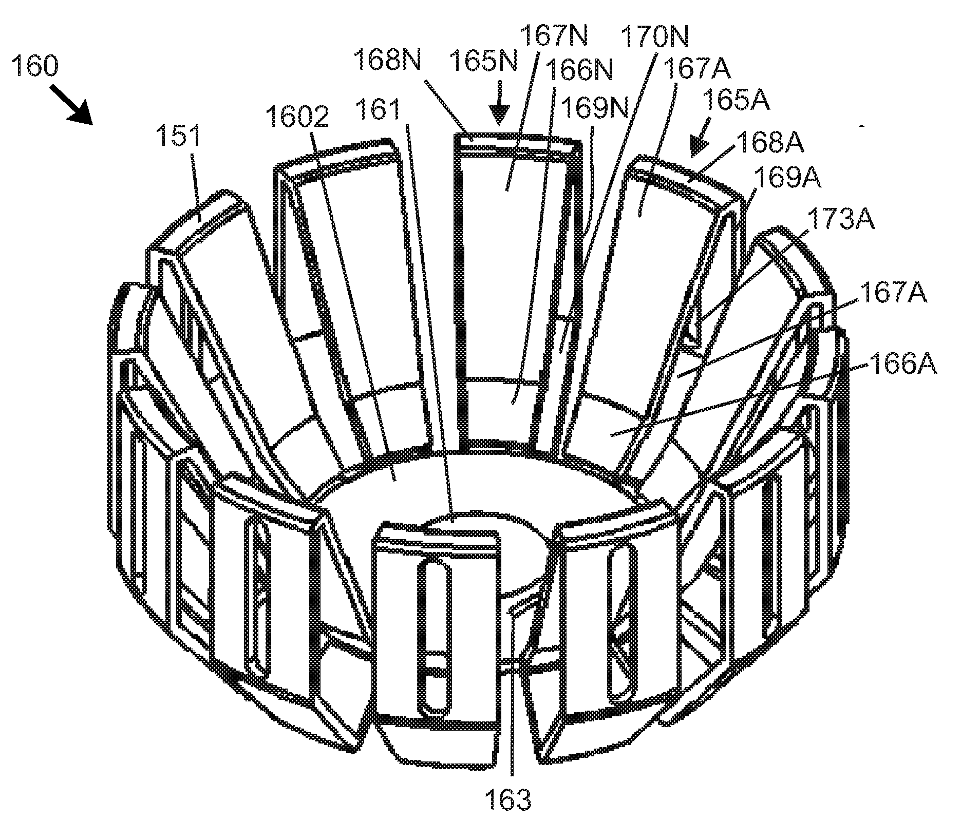
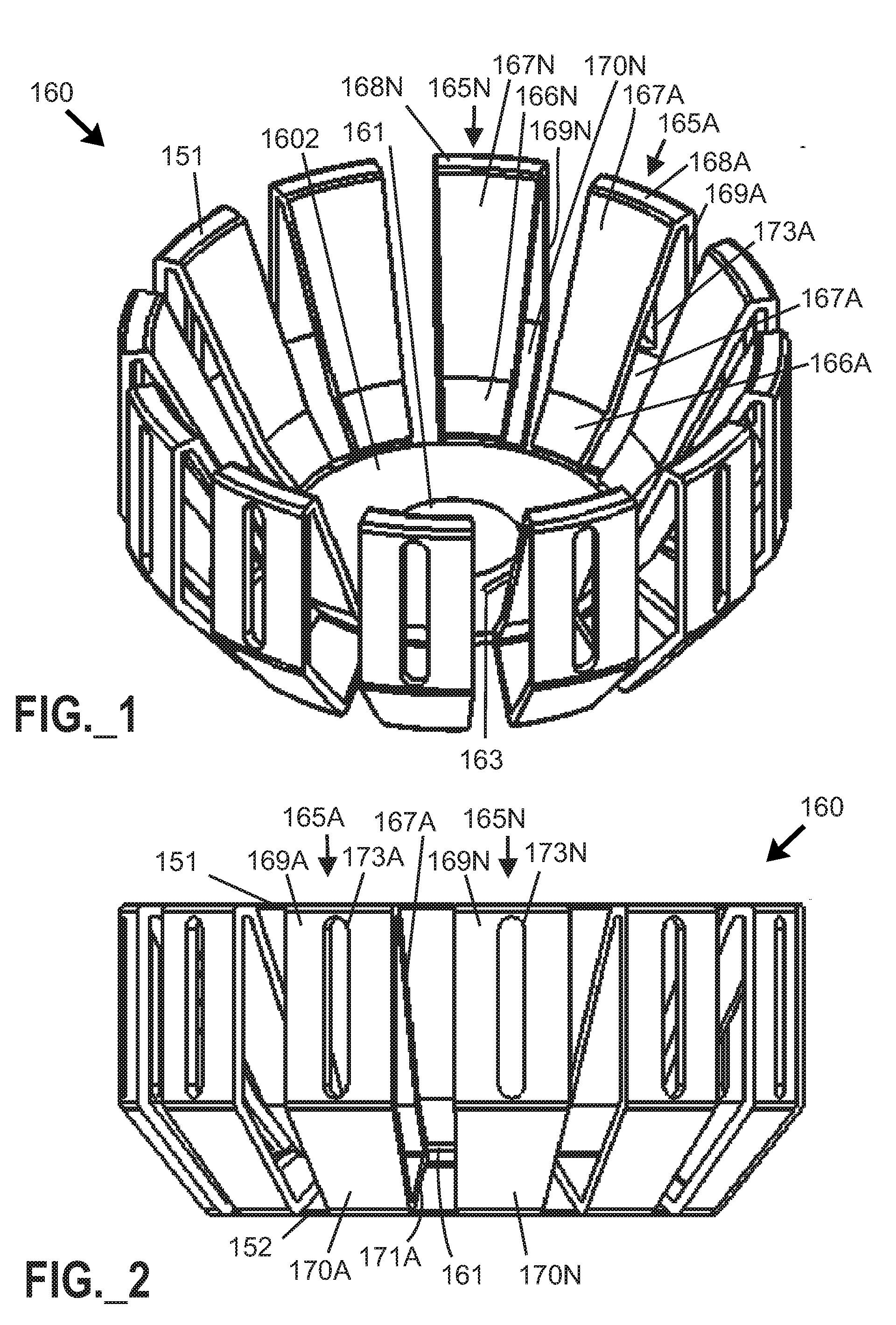
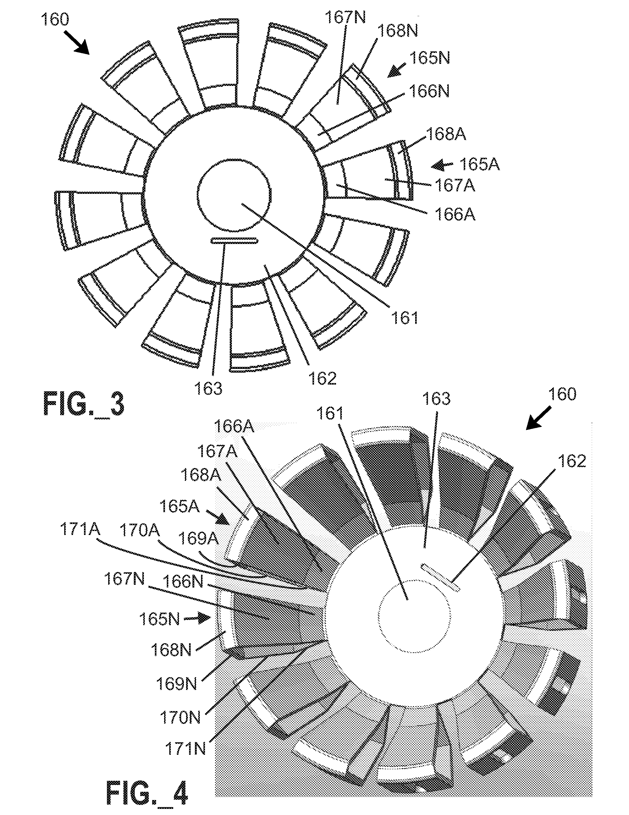
A solid state lighting device includes a device-scale stamped heatsink with a base portion and multiple segments or sidewalls projecting outward from the base portion, and dissipates all steady state thermal load of a solid state emitter to an ambient air environment. The heatsink is in thermal communication with one or more solid state emitters, and may define a cup-like cavity containing a reflector. At least a portion of each one sidewall portion or segment extends in a direction non-parallel to the base portion. A dielectric layer and at least one electrical trace may be deposited over a metallic sheet to form a composite sheet, and the composite sheet may be processed by stamping and / or progressive die shaping to form a heatsink with integral circuitry. At least some segments of a heatsink may be arranged to structurally support a lens and / or reflector associated with a solid state lighting device.

Description

FIELD OF THE INVENTION[0001]The present invention relates to solid state lighting devices, and heat transfer structures relating to same.DESCRIPTION OF THE RELATED ART[0002]Solid state light sources may be utilized to provide white light (e.g., perceived as being white or near-white), and have been investigated as potential replacements for white incandescent lamps. Light perceived as white or near-white may be generated by a combination of red, green, and blue (“RGB”) emitters, or, alternatively, by combined emissions of a blue light emitting diode (“LED”) and a yellow phosphor. In the latter case, a portion of the blue LED emissions pass through the phosphor, while another portion of the blue LED emissions is “downconverted” to yellow; the combination of blue and yellow light provide a white light. Another approach for producing white light is to stimulate phosphors or dyes of multiple colors with a violet or ultraviolet LED source. A solid state lighting device may include, for e...

Claims


Application Information

Patent Timeline
IPC IPC(8): H01L33/00H01L21/00F21V29/00
CPCF21V7/0025F21Y2101/02F21V29/004F21V29/402F21V23/006F21V29/85F21V29/505F21V29/677F21V29/70F21V29/83F21K9/13F21K9/23F21Y2115/10
Inventor PICKARD, PAUL KENNETHMEDENDORP, JR., NICHOLAS W.
Owner IDEAL IND LIGHTING LLC
Learn More