Sheet conveyance device and image forming apparatus using the same device
a conveyancing device and image forming technology, applied in the direction of transportation and packaging, thin material processing, article separation, etc., can solve the problems of large device, high cost, and inability to easily separate sheets, and achieve the effect of simplifying the structure of the device and the apparatus, reducing manufacturing costs, and high reliability
- Summary
- Abstract
- Description
- Claims
- Application Information
AI Technical Summary
Benefits of technology
Problems solved by technology
Method used
Image

Examples
embodiment 1
[0036][Constitutional Example of Image Forming Apparatus 100]
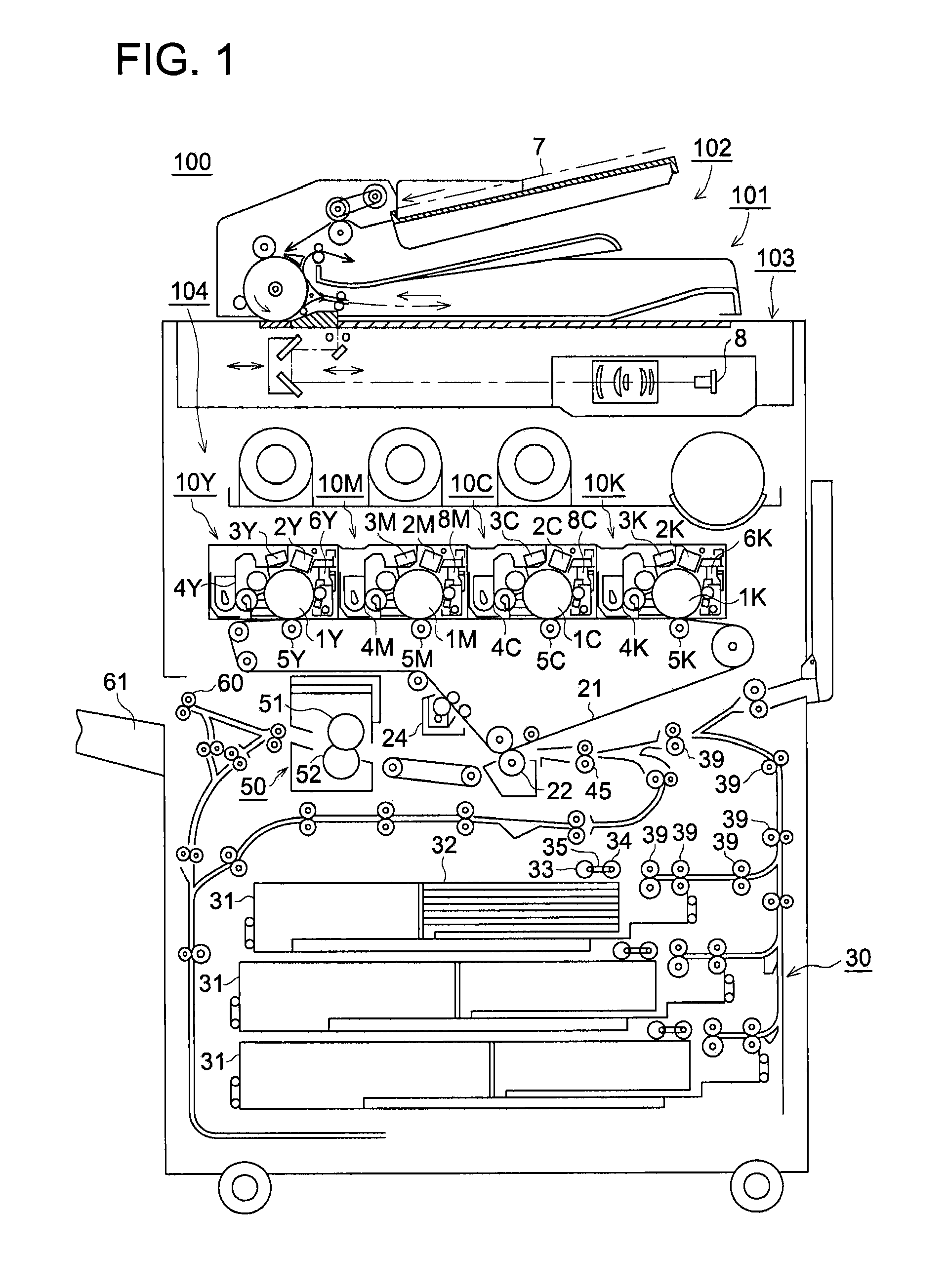
[0037]FIG. 1 is a schematic drawing to show a constitutional example of image forming apparatus 100, relating to Embodiment 1 of the present invention. In FIG. 1, image forming apparatus 1 is structured of image forming section 104, image reading device 101, sheet conveyance device 30, and image fixing device 50. Image forming section 104 is referred to as a tandem type full color image forming section, said image forming section 104 is structured of image forming units 10Y, 10M, 10C and 10K, intermediate transfer body 21, secondary transfer section 22, and cleaning section 24 to clean intermediate transfer body 21.
[0038]Image reading device 101, structured of automatic document feeding device 102, and scanning exposure device 103, is provided above image forming section 104. Original document 7, placed on a platen of automatic document feeding device 102, is conveyed by a conveyance section, which is not illustrated. Imag...
embodiment 2
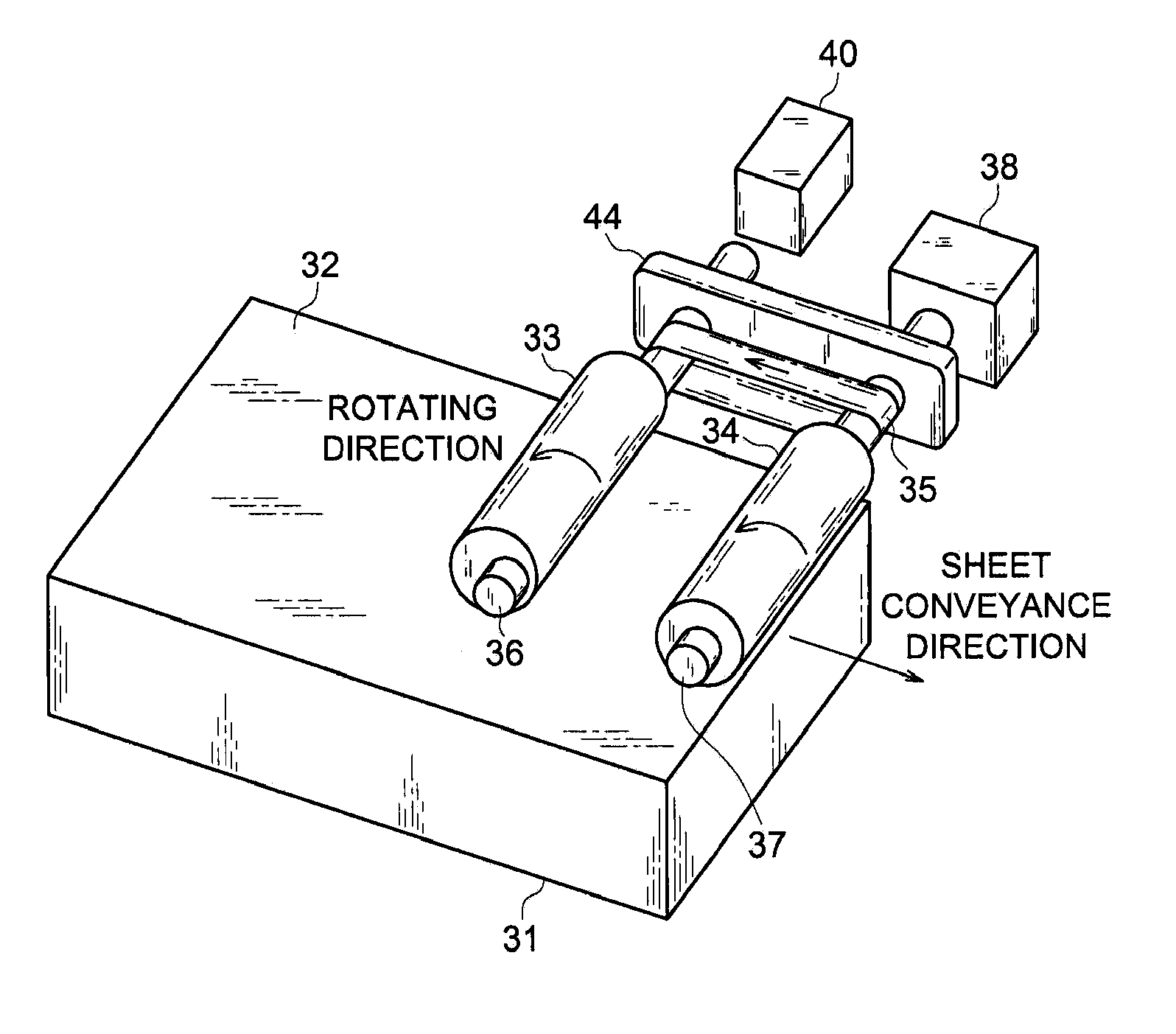
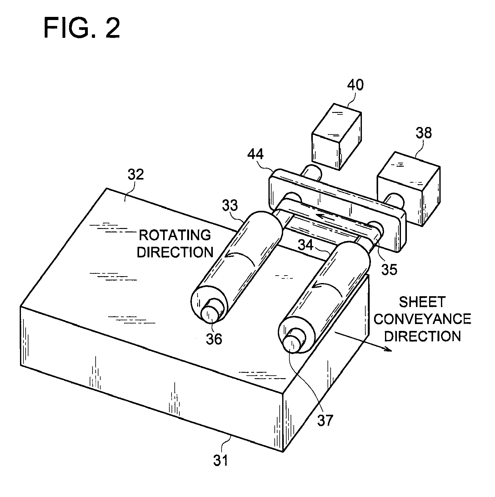
[0071]In Embodiment 2, the operational example of sheet conveyance device 30A will be detailed. Embodiment 2 includes eccentric roller 33 and conveyance roller 34, used in sheet conveyance device 30 of Embodiment 1, but the positions of both rollers are changed relative to each other in Embodiment 2. Various parts used in Embodiment 2, whose names and identifying numbers are the same as those in Embodiment 1, and exhibit the same functions as those of Embodiment 1, so that detailed explanations for them will be omitted.
[0072]FIGS. 6A-6E show the operational example of sheet conveyance device 30A, relating to Embodiment 2. In those figures, sheet conveyance device 30A is structured of conveyance roller 33A, eccentric roller 34A, and coupling belt 35.
[0073]In FIGS. 6A-6E, eccentric roller 34A goes through a full rotation. That is, when drive motor 38 is rotated counterclockwise, which motor is connected to roller shaft 36A, conveyance roller 33A rotates counterclockwise, and eccentric...
embodiment 3
[0081]In Embodiment 3, conveyance roller 34 of sheet conveyance device 30 of Embodiment 1 is exchanged for another eccentric roller 34B, that is, two eccentric rollers 34B are provided on sheet conveyance device 30B of Embodiment 3. Various parts in Embodiment 3, whose names and identifying numbers are the same as those in Embodiment 1, and exhibit the same functions as those of Embodiment 1, so that detailed explanations for them will be omitted.
[0082]FIGS. 7A-7E show the example of the operation of sheet conveyance device 308 relating to Embodiment 3. Sheet conveyance device 308 is structured of a first eccentric roller (hereinafter referred to as “eccentric roller 33B”), a second eccentric roller (hereinafter referred to as “eccentric roller 34B”), and coupling belt 35.
[0083]In FIGS. 7A-7E, when drive motor 38 (being not illustrated), which is connected to a first eccentric shaft (hereinafter referred to as “eccentric roller shaft 36B”), rotates counterclockwise, so that eccentri...
PUM
| Property | Measurement | Unit |
|---|---|---|
| distance | aaaaa | aaaaa |
| peripheral length | aaaaa | aaaaa |
| contacting force | aaaaa | aaaaa |
Abstract
Description
Claims
Application Information
 - R&D
- Intellectual Property
- Life Sciences
- Materials
- Tech Scout
- Unparalleled Data Quality
- Higher Quality Content
- 60% Fewer Hallucinations
Browse by: Latest US Patents, China's latest patents, Technical Efficacy Thesaurus, Application Domain, Technology Topic, Popular Technical Reports.
© 2025 PatSnap. All rights reserved.Legal|Privacy policy|Modern Slavery Act Transparency Statement|Sitemap|About US| Contact US: help@patsnap.com