Modular stacked subsea power system architectures

a power system and module technology, applied in the field of modular stacked subsea power system architectures, can solve the problems of reducing material and installation costs, affecting system cost, system complexity, efficiency and power density, and a dominant portion of overall system cos

Inactive Publication Date: 2010-06-03
GENERAL ELECTRIC CO
View PDF8 Cites 121 Cited by
  • Summary
  • Abstract
  • Description
  • Claims
  • Application Information

AI Technical Summary

Problems solved by technology

They significantly affect system cost, reliability / maintainability, system complexity, efficiency and power density.
For example, offshore or subsea cables for power transmission typically form a dominant portion of overall system cost.
Compared with three-phase AC power transmission, DC power transmission reduces the number and weight of cables, thus potentially reducing material and installation costs.
However, it has inherent limitations for long distance and high power subsea or offshore applications, or even for applications with short distance but with limited capacity margins of the power source.
This results in higher cable losses, higher current ratings and larger and more costly cables, and higher voltage losses along the cable.
These issues are exacerbated for long distance and high power transmission for oil and gas subsea projects.
Even for short distance power transmission / distribution, these issues still exist for applications with a limited capacity margin of the power source.
For example, for electric loads that are tied back to an existing power infrastructure on a offshore platform with limited capacity margin, a relatively large amount of reactive power may trigger power system stability issues or exceed current rating limits of the power source.
However, this solution is at the expense of proportionally increased size of magnetic components, such as transformers.
At high power levels, the size and weight penalty would be excessive.
Those special power switches (valves) and large filters would make existing high voltage direct current technology an expensive and bulky solution for subsea applications.

Method used


Image

  • Modular stacked subsea power system architectures
  • Modular stacked subsea power system architectures
  • Modular stacked subsea power system architectures

Examples


Embodiment Construction

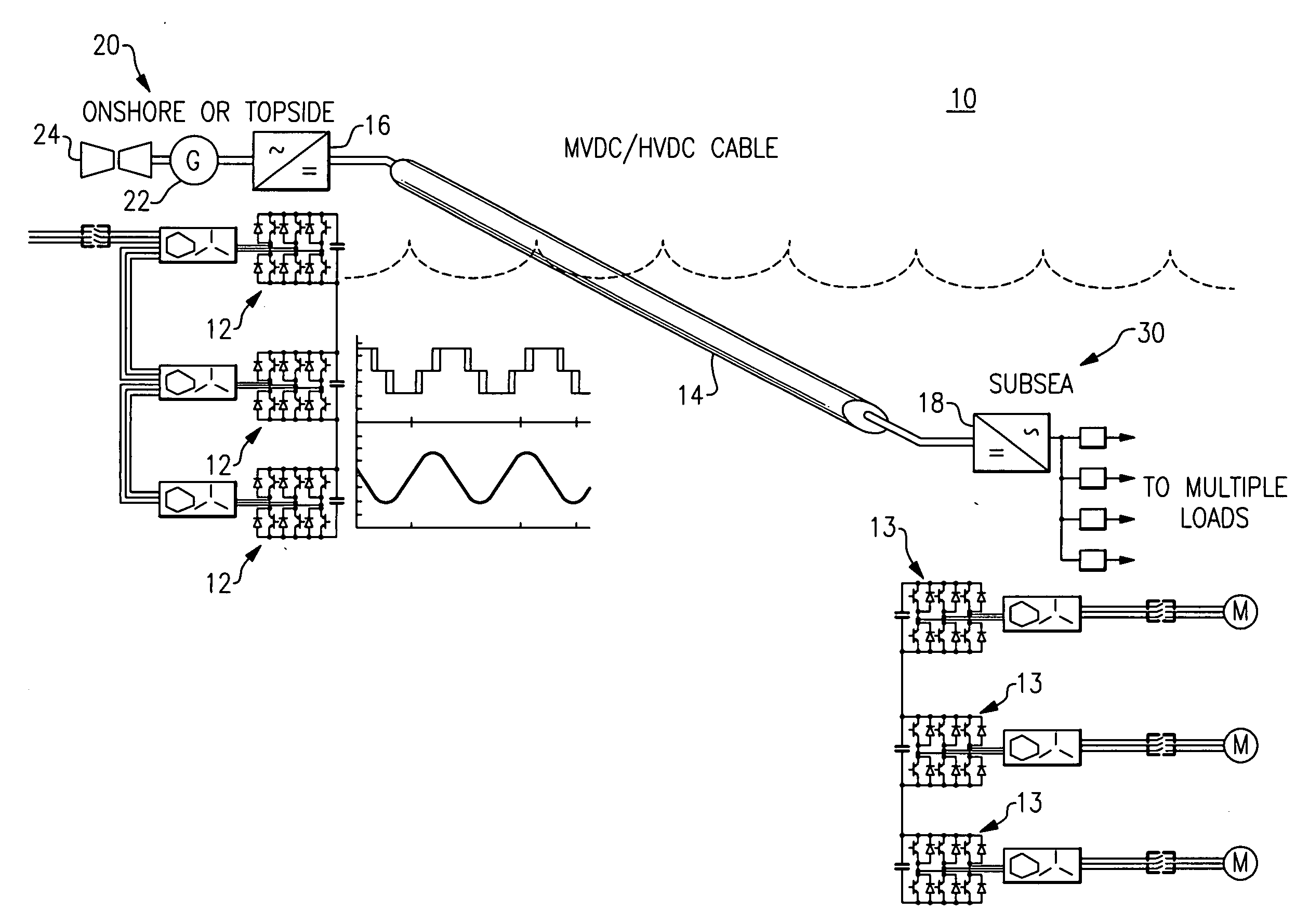
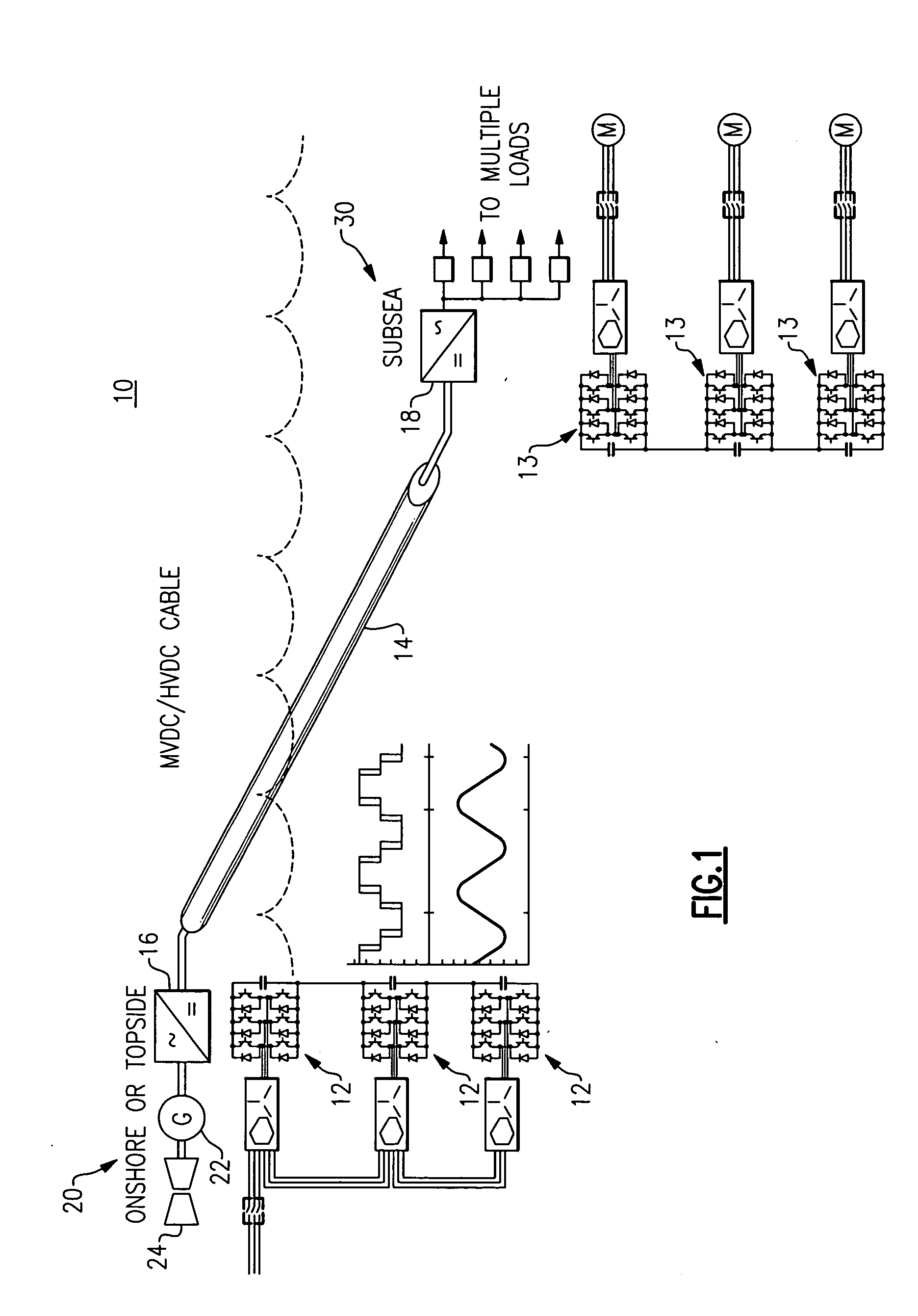
[0025]FIG. 1 is a simplified diagram illustrating a sub-sea power delivery system 10 with modular stacked power converter building blocks 12, 13 on both the top-side / on-shore side and sub-sea side of the system according to one embodiment of the invention. The sub-sea power delivery system 10 includes a system DC transmission link / bus (cable) 14 that may be a medium voltage direct current (MVDC) or high voltage direct current (HVDC) cable, wherein the transmission DC bus 14 is configured to carry power from a top-side or on-shore power module 16 to at least one sub-sea load module 18. Both the power module 16 and the sub-sea load module 18 each may include one or more respective stacked modular power converter building blocks 12, 13. Each modular power converter building block 12, 13 comprises a modular power converter such as a DC to AC inverter, AC to AC converter, DC to DC converter, or AC to DC inverter, that is common to many known types of motor drives; and therefore the power...


PUM


Abstract

A sub-sea power delivery system includes a plurality of modular power converter building blocks on each of the power source side and the sub-sea load side that are stacked and interconnected to meet site expansion requirements and electrical load topologies. The power delivery system comprises a system DC transmission link/bus, wherein the system DC link is configured to carry HVDC or MVDC power from an onshore utility or topside power source to multiple sub-sea load modules. The stacked modular power converter topology on the sub-sea side of the sub-sea power delivery system is symmetrical with the stacked modular power converter topology on the on-shore/top-side of the sub-sea power delivery system.

Description

CLAIM TO PRIORITY OF PROVISIONAL APPLICATION[0001]This application claims priority under 35 U.S.C. §119(e)(1) of provisional application Ser. No. 61 / 119,490, filed Dec. 3, 2008, by Richard S. Zhang et al.BACKGROUND[0002]This invention relates generally to electrical power delivery systems for offshore and sub-sea electrical loads via a direct current (DC) transmission bus. The receiving end and sending end of the DC transmission bus each comprise modular stacked power converters that are symmetrical in structure. The receiving end converters are reconfigurable based on site expansion requirements and on load types and configurations.[0003]There is a growing industry need to deliver power, more effectively with lower cost and higher reliability / maintainability, efficiency and power density, from onshore or offshore platforms to electric loads at seabed or remote offshore locations, or vice versa in a reverse power flow direction for offshore power generation tie-back. This growing ne...

Claims


Application Information

Patent Timeline
Patent Type & Authority Applications(United States)
IPC IPC(8): H02J3/36
CPCH02M5/458H02M7/483H02M7/003H02J3/36Y02E60/60H02B7/08H02J3/00H02J3/20H02J3/38H02M7/12
Inventor ZHANG, RICHARD S.DATTA, RAJIBSIHLER, CHRISTOF MARTINSONG MANGUELLE, JOSEPH
Owner GENERAL ELECTRIC CO
Why Eureka
Try Eureka