Power transfer apparatus and method for transferring electric power

a technology of power transfer apparatus and electric power, which is applied in the direction of exchanging data chargers, inductances, transportation and packaging, etc., can solve problems such as time lag, and achieve the effect of reducing the time lag and reducing the amount of digital data to be transferred

Inactive Publication Date: 2010-06-03
KK TOSHIBA
View PDF3 Cites 14 Cited by
  • Summary
  • Abstract
  • Description
  • Claims
  • Application Information

AI Technical Summary

Benefits of technology

[0009]Accordingly, an advantage of the present invention is to provide a power transfer apparatus configured to transfer a signal for feeding a secondary output voltage transferred through contactless power transfer back to the primary side without a need of a broad frequency bandwidth. The power transfer apparatus is configured to reduce a time lag by reducing digital data to be transferred. The power transfer apparatus is configured to immediately react to a steep change of the secondary output voltage.
[0010]To achieve the above advantage, one aspect of the present invention is that a power transfer apparatus including a first device and a second device having a first coil and a second coil, respectively, is provided. The first device is configured to produce primary power through the primary coil upon being supplied with external power and to be controlled by a provided control signal so that the primary power decreases and increases upon the control signal representing a first value and a second value, respectively. The second device is configured to be joined with the first device so that the secondary coil is electromagnetically coupled with the primary coil. The second device is configured to produce secondary power upon the secondary coil being driven through the electromagnetic coupling. The second device is configured to provide the first device with the control signal representing the first value and the second value upon the secondary power being greater and smaller than a reference value, respectively.

Problems solved by technology

The signal transfer of JP-A-2003-348775 may thereby cause a time lag, and is possibly unable to react to a steep change of the secondary output voltage.

Method used


Image

  • Power transfer apparatus and method for transferring electric power
  • Power transfer apparatus and method for transferring electric power
  • Power transfer apparatus and method for transferring electric power

Examples


first embodiment

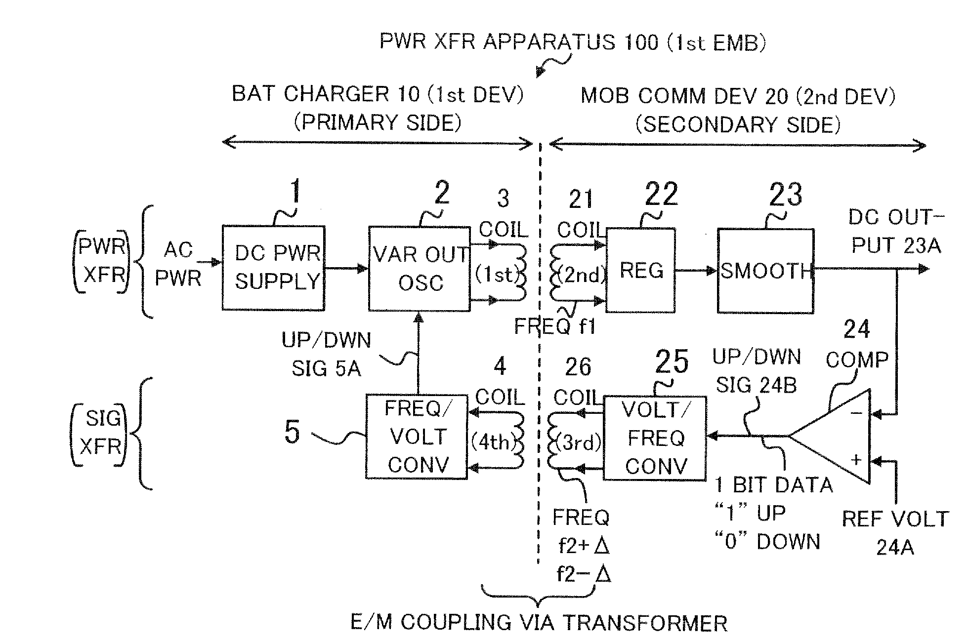
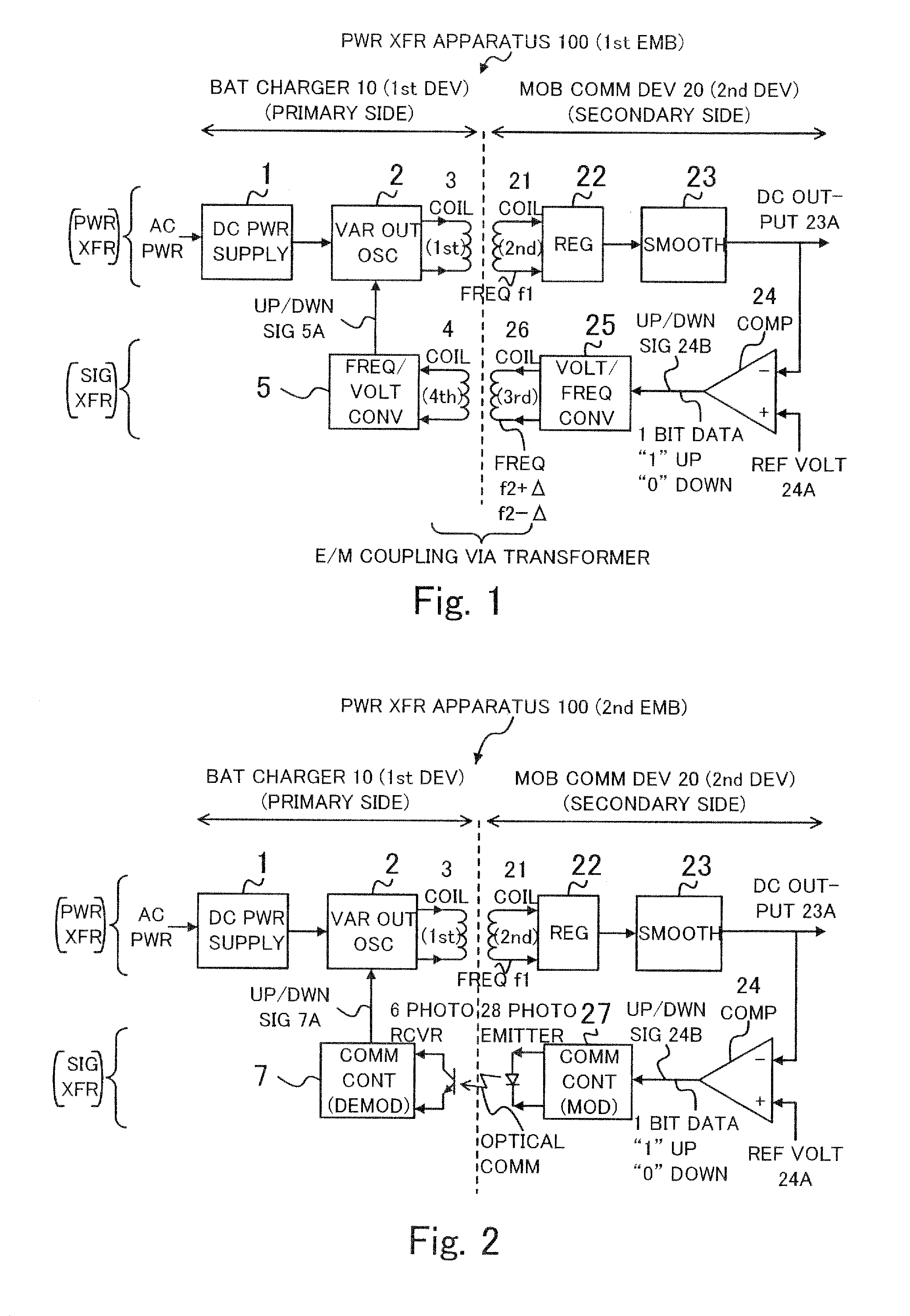
[0014]FIG. 1 is a block diagram of a power transfer apparatus 100 of the present invention. The power transfer apparatus 100 includes a battery charger 10 (first device on the primary side) and a mobile communication device 20 (second device on the secondary side). The mobile communication device 20 can be easily put on and taken off the battery charger 10. The power transfer apparatus 100 transfers electric power and a signal while the mobile communication device 20 is being put on the battery charger 10.

[0015]An upper half of FIG. 1 shows a portion of the power transfer apparatus 100 for transferring electric power from the battery charger 10 to the mobile communication device 20. A lower half of FIG. 1 shows a portion of the power transfer apparatus 100 for transferring a signal from the mobile communication device 20 to the battery charger 10 so as to control feedback for making an output of the power transferred to the mobile communication device 20 stable.

[0016]The configurati...

second embodiment

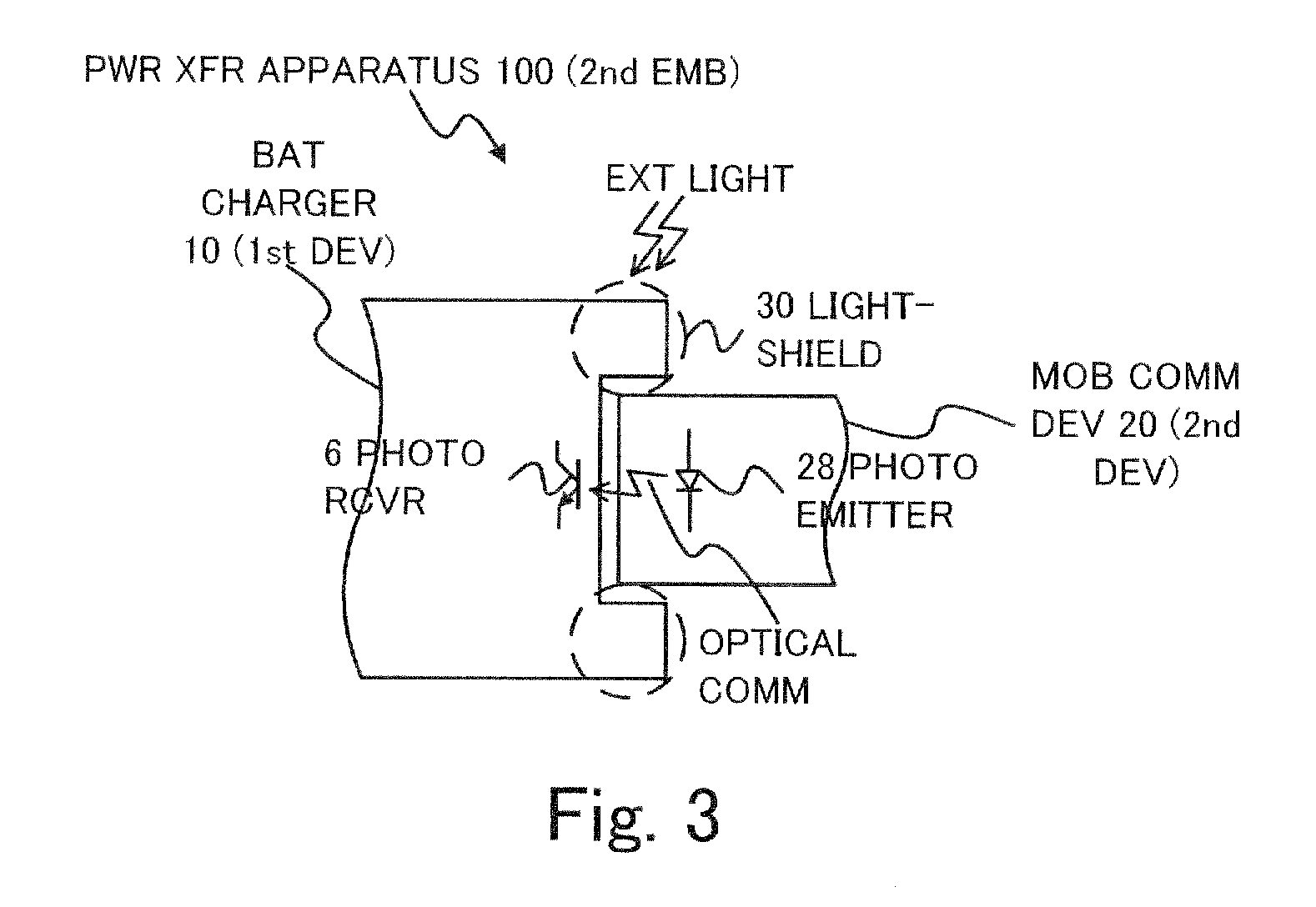
[0035]FIG. 3 shows a structure of an optical communication portion of the power transfer apparatus 100 of the present invention. A lightshield 30 is provided so that the optical communication between the photo emitter 28 and the photo receiver 6 is not affected by external light upon the mobile communication device 20 being put on the battery charger 10. The power transfer apparatus 100 can thereby perform stable optical communication without being affected by external light.

[0036]The photo emitter 28 and the photo receiver 6 are configured to be separate and the one of them can be easily put on and taken off the other of them so that the mobile communication device (second device) can be put on and taken off the battery charger 110 (first device). For another power transfer apparatus constituted by a first device and a second device integrated with and fixed to each other, though the photo emitter 28 and the photo receiver 6 may form a photo coupler and so on by being Integrated wi...


PUM

PropertyMeasurementUnit
poweraaaaaaaaaa
frequencyaaaaaaaaaa
output voltageaaaaaaaaaa

Abstract

A power transfer apparatus including a first device and a second device having a first coil and a second coil, respectively, is provided. The first device is configured to produce primary power through the primary coil upon being supplied with external power and to be controlled by a provided control signal so that the primary power decreases and increases upon the control signal representing a first value and a second value, respectively. The second device is configured to be joined with the first device so that the secondary coil is electromagnetically coupled with the primary coil. The second device is configured to produce secondary power upon the secondary coil being driven through the electromagnetic coupling. The second device is configured to provide the first device with the control signal representing the first value and the second value upon the secondary power being greater and smaller than a reference value, respectively.

Description

CROSS REFERENCE TO RELATED APPLICATIONS[0001]This application is based upon and claims the benefit of priority from the prior Japanese Patent Application No. 2008-305041 filed on Nov. 28, 2008; the entire contents of which are incorporated herein by reference.BACKGROUND OF THE INVENTION[0002]1. Field of the Invention[0003]The present invention relates to a power transfer apparatus and a method for transferring electric power, and in particular to a power transfer apparatus adapted for contactless power transfer not through an electrical contact. The power transfer apparatus is configured to feed a secondary output voltage back to a primary side so as to make the secondary output voltage stable.[0004]2. Description of the Related Art[0005]An apparatus configured to transfer electric power by means of electromagnetic induction of a transformer is known, as disclosed in Japanese examined patent application publication (Toroku), No. B-3416863. According to paragraphs 0167-0168 and FIG. ...

Claims


Application Information

Patent Timeline
Patent Type & Authority Applications(United States)
IPC IPC(8): H01F38/14H02J7/00H02M3/28
CPCH02J7/025H01F2038/143H02J50/10H02J7/00034
Inventor SATO, MASAKI
Owner KK TOSHIBA
Why Eureka
Try Eureka