Torque support member for rotating electrical machine

a technology of rotating electrical machines and support members, which is applied in the direction of rotating parts of magnetic circuits, superconductor devices, magnetic circuit shapes/forms/construction, etc., can solve the problems of increasing the flux densities of the machines, increasing the magnetomotive force generated by the windings, and the superconducting windings need cryogenic temperatures to operate properly, etc., to improve the reliability of the machine, reduce the overall cost of the generator, and reduce the cost and/or complexity

Active Publication Date: 2010-06-03
AMERICAN SUPERCONDUCTOR
View PDF6 Cites 14 Cited by
  • Summary
  • Abstract
  • Description
  • Claims
  • Application Information

AI Technical Summary

Benefits of technology

[0010]The support member is modular in construction and can be pre-assembled separately from, and externally of, the rotor assembly, and then easily attached to the rotor body at the time of machine assembly. Pre-assembly permits support straps within the support member to be pre-tensioned and tested before connection to the rotor body, improving machine reliability.
[0011]The disclosed generator employs an iron rotor body, which is advantageous since the magnetic flux generated by the iron rotor body means that less superconductor material is required to achieve the same power output. In effect, this lowers the overall cost of the generator since the cost and / or complexity of the superconducting windings are also reduced. However, the structure of the iron rotor body is such that very little space is permitted for support of the rotor winding assembly. Here, the low profile of the support member is advantageous since it provides adequate rotor winding assembly support while permitting use of the iron core within the generator.

Problems solved by technology

The use of superconducting windings in these machines has resulted in a significant increase in the magnetomotive forces generated by the windings and increased flux densities in the machines.
However, superconducting windings require cryogenic temperatures to operate properly.

Method used


Image

  • Torque support member for rotating electrical machine
  • Torque support member for rotating electrical machine
  • Torque support member for rotating electrical machine

Examples


Embodiment Construction

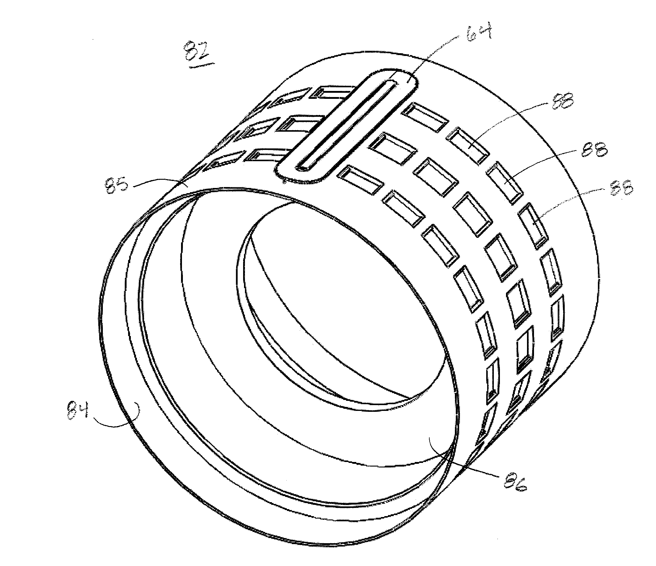
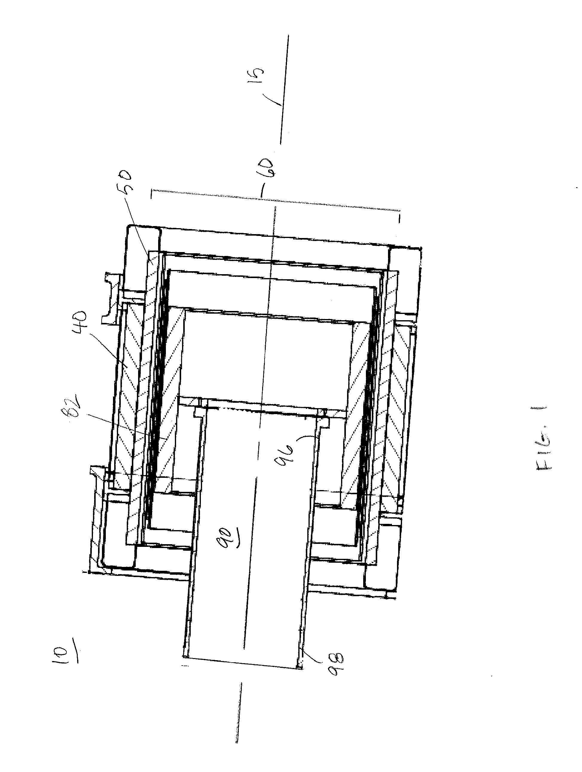
[0022]Referring now to FIG. 1, generator 10 is a rotating superconducting machine that includes a rotor assembly 60 and a stator assembly 40. As will be described in greater detail below, the rotor assembly 60 is supported within the stator assembly 40 so that the rotor and stator assemblies are coaxial with each other and a longitudinal axis 15 of the generator 10.

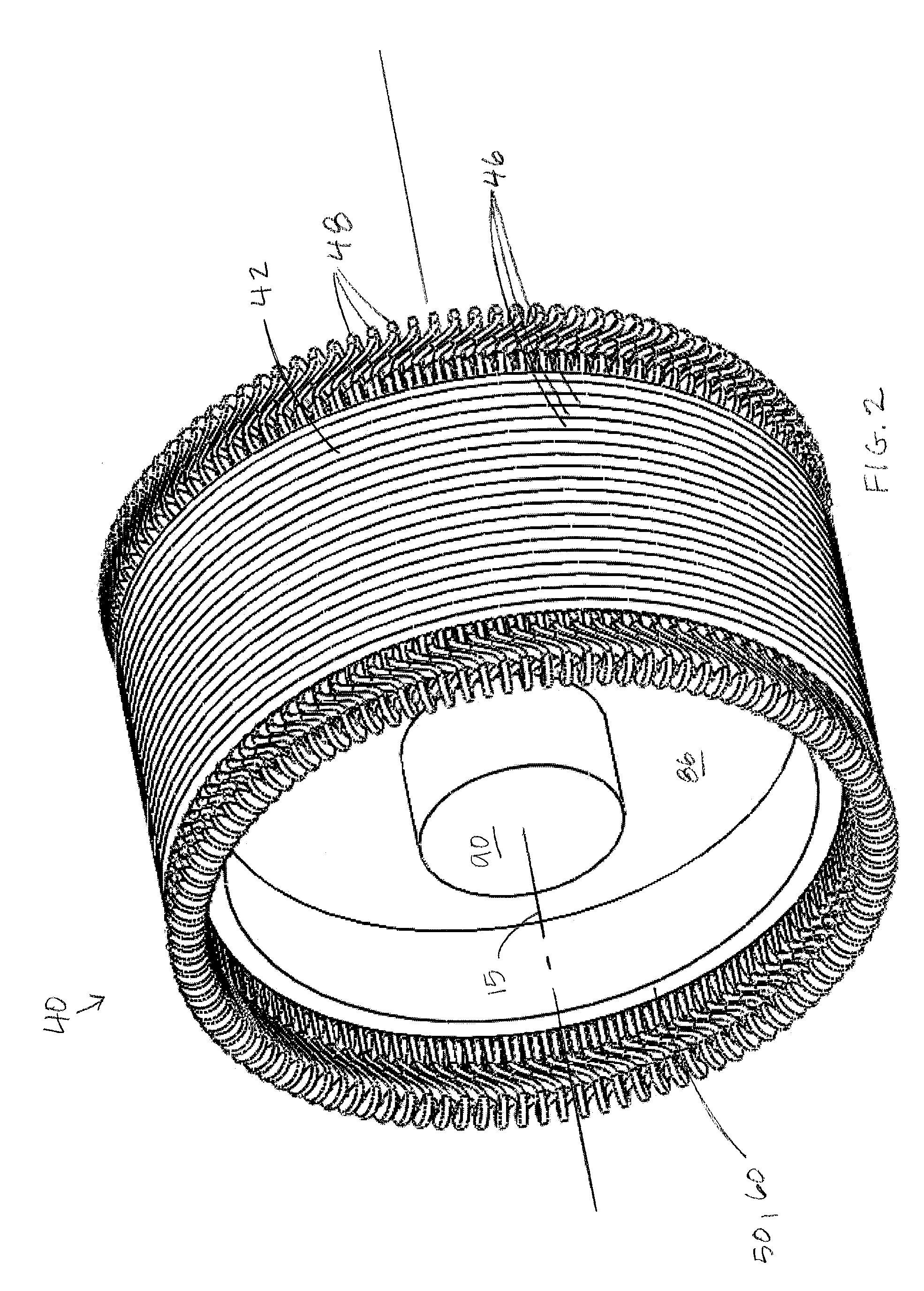
[0023]Referring to FIG. 2, the stator assembly 40 includes a stator core 42 and stator windings 48 supported within the stator core 42. The stator core 42 is a hollow cylindrical body that is an assembly of laminated annular ferromagnetic plates 46. The stator windings are formed of transposed wire cables (not shown), in which the individual copper wire conductors (not shown) are twisted and / or woven to form a pattern which reduces conduction losses. The transposed cables may include Litz wire, Rutherford wire, Robel wire, or any other suitable transposed wire. The transposed cables are wound around an axis transverse to ...


PUM


Abstract

A support module is provided for use in a rotor assembly of a rotating machine. The support module is disposed on the rotor body, supports high temperature superconductor rotor windings within the rotor assembly, and thermally decouples the cold portions of the rotor assembly, including windings and support tube, from the ambient temperature rotor body and drive shaft. The support module includes a frame disposed on the rotor body, a support block connected to the rotor winding and suspended within the frame, and thermally non-conductive straps extending from each of a pair of opposed sides of the support block to the frame, the straps suspending the support block within the frame.

Description

GOVERNMENT RIGHTS STATEMENT[0001]The U.S. Government has a paid-up license in this invention and the right in limited circumstances to require the patent owner to license others on reasonable terms as provided for by the terms of Contract No. 70 NANB7H7055 awarded by the National Institute of Standards and Technology / Advanced Technology Program.BACKGROUND OF THE INVENTION[0002]Superconducting generators have been under development since the early 1960s. The use of superconducting windings in these machines has resulted in a significant increase in the magnetomotive forces generated by the windings and increased flux densities in the machines. However, superconducting windings require cryogenic temperatures to operate properly. Thus, higher torque motors and generators are being developed to include mechanisms for transferring torque between a rotor winding assembly and an output shaft while limiting heat transported to the cryogenic region of the machine.SUMMARY[0003]In one aspect, ...

Claims


Application Information

Patent Timeline
Patent Type & Authority Applications(United States)
IPC IPC(8): H02K3/46
CPCH02K3/47Y02E40/625H02K55/04H02K7/1838Y02E10/72Y02E40/60
Inventor WINN, PETER M.
Owner AMERICAN SUPERCONDUCTOR
Why Eureka
Try Eureka