Hysteretic switching regulator and control method used therein

a switching regulator and hysteretic technology, applied in the direction of power conversion systems, instruments, dc-dc conversion, etc., can solve the problems of large amount of ripple voltage superimposed on the output voltage, low power conversion efficiency of the voltage regulator, and large amount of power required to operate an electronic circui

Active Publication Date: 2010-06-03
RICOH KK
View PDF10 Cites 56 Cited by
  • Summary
  • Abstract
  • Description
  • Claims
  • Application Information

AI Technical Summary

Problems solved by technology

However, using a faster clock signal often results in a larger amount of power required to operate an electronic circuit, since power consumption in individual circuit components increases proportionally to the clock rate at which they are operated.
A drawback encountered by such a conventional design is that using a current sensing resistor affects current-voltage characteristics and results in significant power dissipation, leading to low power conversion efficiency of the voltage regulator.
Other drawbacks include a relatively large amount of ripple voltage superimposed on the output voltage, and variations in the operating frequency caused by variations in input and output voltages.
Such a ripple voltage can be considerable and can adversely affect proper operation of a load circuit connected to an output terminal of the hysteretic regulator.
Another drawback is high costs involved in using the unity gain buffer 122 in the switching regulator 100, which is designed to operate with relatively high switching frequencies to meet today's requirements for high efficiency and compact power supply circuitry.
That is, when operated at a high switching frequency, the analog buffer 122 consumes large amounts of power and requires a relatively large circuit area for proper phase compensation, which can negate some advantages of using a switching voltage regulator.

Method used


Image

  • Hysteretic switching regulator and control method used therein
  • Hysteretic switching regulator and control method used therein
  • Hysteretic switching regulator and control method used therein

Examples


Embodiment Construction

[0033]In describing exemplary embodiments illustrated in the drawings, specific terminology is employed for the sake of clarity. However, the disclosure of this patent specification is not intended to be limited to the specific terminology so selected, and it is to be understood that each specific element includes all technical equivalents that operate in a similar manner and achieve a similar result.

[0034]Referring now to the drawings, wherein like reference numerals designate identical or corresponding parts throughout the several views, examples and exemplary embodiments of this disclosure are described.

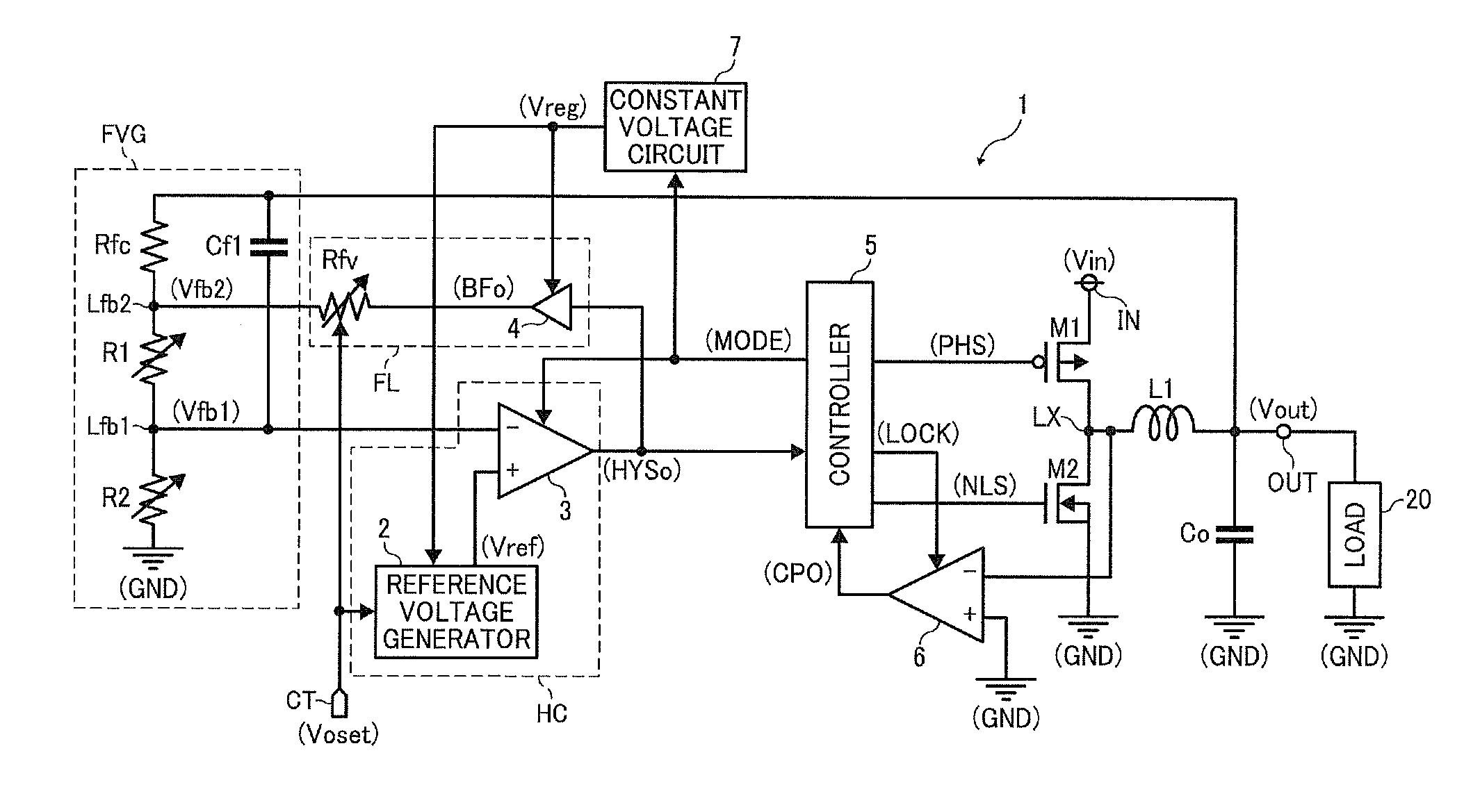
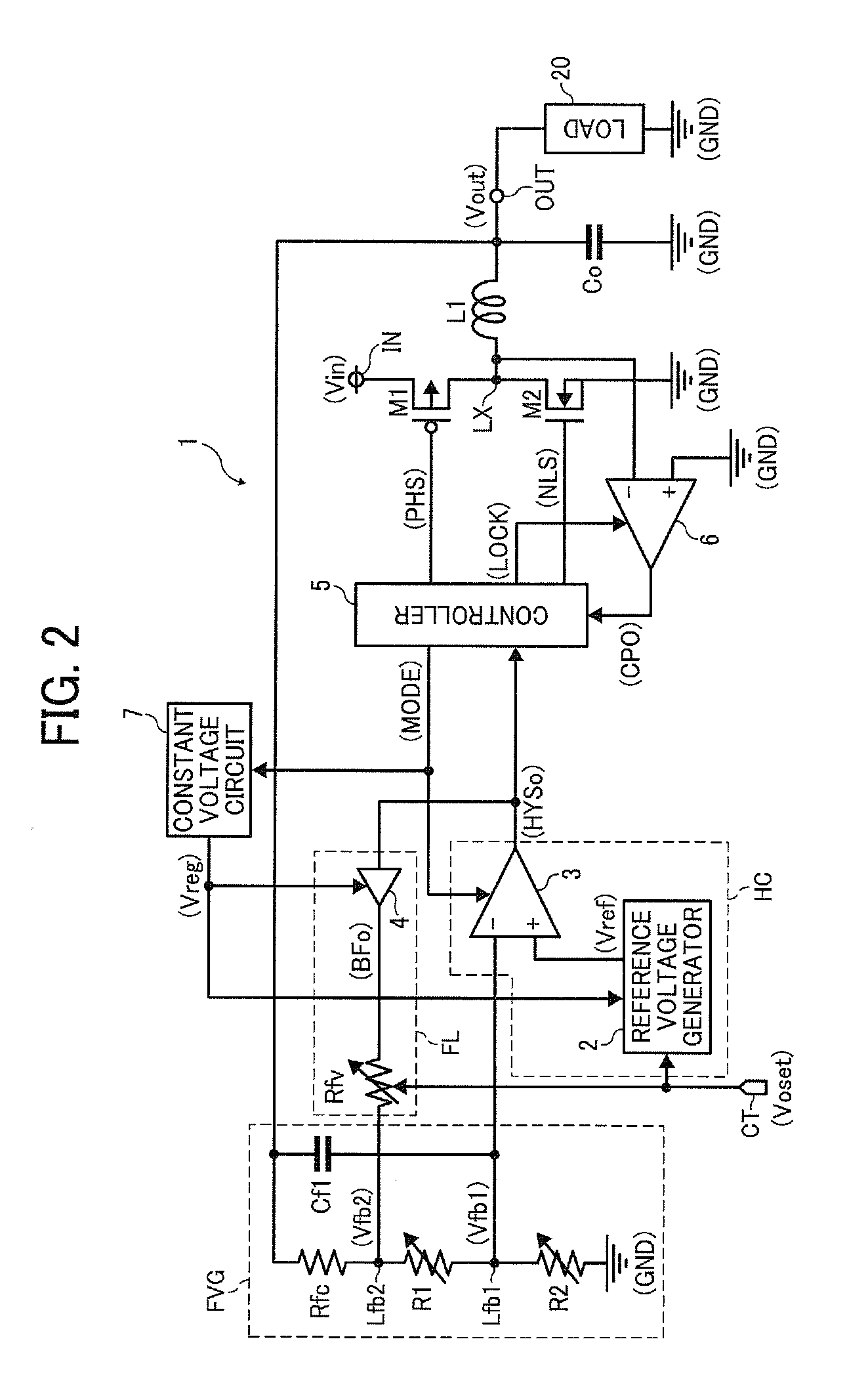
[0035]FIG. 2 is a circuit diagram illustrating a hysteretic switching regulator 1 according one embodiment of this patent specification.

[0036]As shown in FIG. 2, the hysteretic switching regulator 1 is a non-isolated, variable-output step-down or buck voltage regulator with synchronous rectification, which converts an input voltage Vin supplied to an input terminal IN into an outp...


PUM


Abstract

A switching regulator includes a switching transistor, an inductor, a feedback voltage generator, a hysteresis comparator circuit, and a feedback loop circuit. The switching transistor alternately switches on and off. The inductor charges when the switching transistor is on. The feedback voltage generator generates a first feedback voltage by dividing an output voltage. The hysteresis comparator circuit has a voltage comparator to compare the first feedback voltage against a reference voltage to output a comparator output signal as a result of the comparison. The feedback loop circuit feeds the comparator output signal back to the feedback voltage generator to generate a second feedback voltage. The first feedback voltage has an alternating current component substantially dependent on the second feedback voltage varying with the comparator output signal.

Description

BACKGROUND OF THE INVENTION[0001]1. Technical Field[0002]The present invention relates to a hysteretic switching regulator and a control method thereof, and more particularly, to a variable-output, hysteretic switching voltage regulator having an operating frequency insensitive to variations in input and output voltages and a control method for use in such a voltage regulator.[0003]2. Discussion of the Background[0004]With currently increasing concern for environmental and ecological issues, there is a growing need for power-efficient electronic equipment. Reducing power consumption is doubly important for battery-powered electronic devices, such as mobile phones and digital cameras, since it not only contributes to preserving the environment but also extends the lifetime of batteries commonly used in such hand-held portable electronics.[0005]On the other hand, most modern electronic products process large amounts of data as they become capable of recording, processing, and displayi...

Claims


Application Information

Patent Timeline
Patent Type & Authority Applications(United States)
IPC IPC(8): G05F1/00
CPCH02M3/1563
Inventor NISHIDA, JUNJI
Owner RICOH KK
Why Eureka
Try Eureka