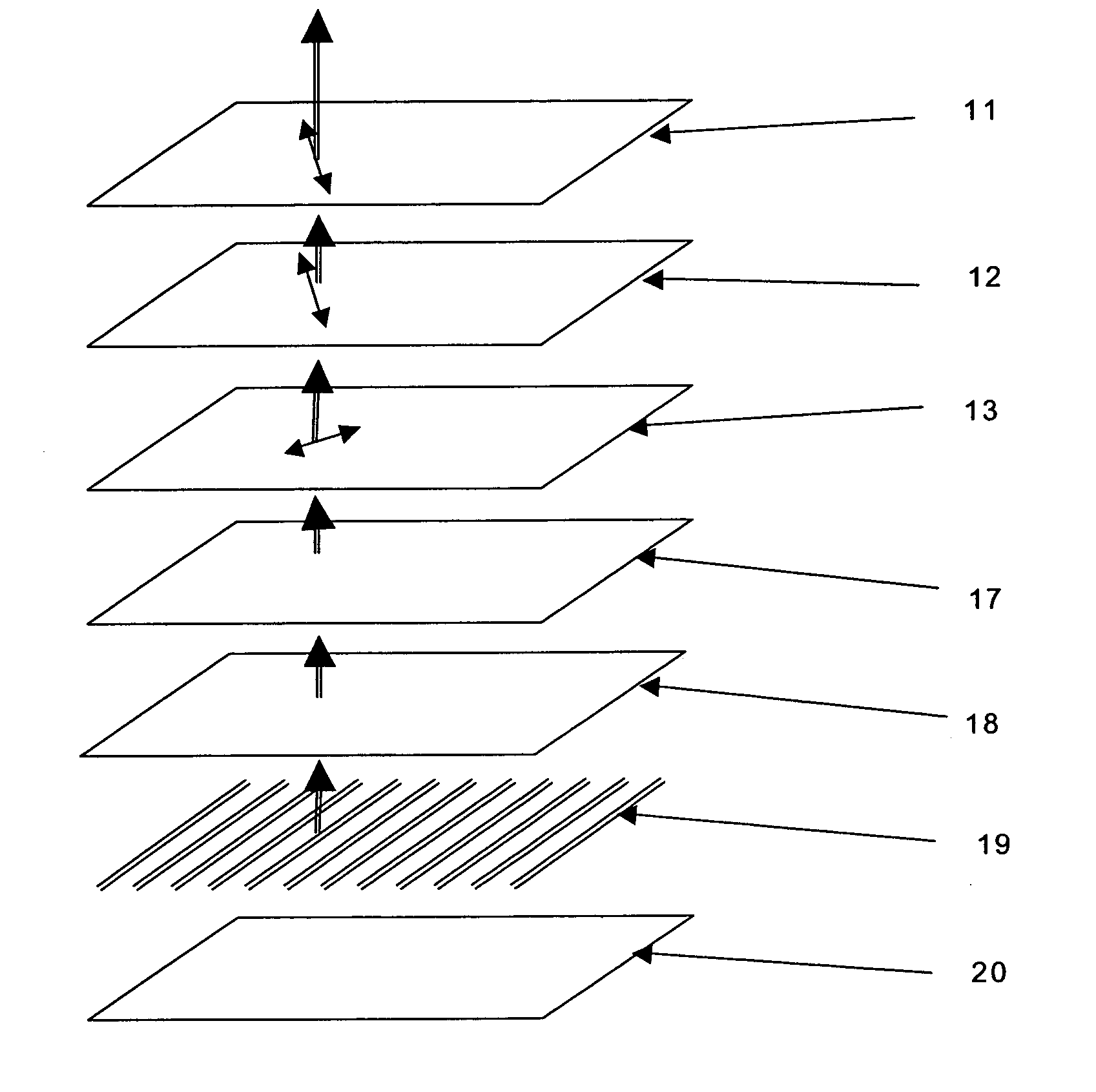
Optical Element, Polarizing Plate, Retardation Plate, Illuminating Device and Liquid Crystal Display

a technology of polarizing plate and retardation plate, which is applied in the direction of polarizing element, lighting and heating apparatus, instruments, etc., to achieve the effect of widened color reproduction rang

Inactive Publication Date: 2010-06-03
ZEON CORP
View PDF5 Cites 5 Cited by
  • Summary
  • Abstract
  • Description
  • Claims
  • Application Information

AI Technical Summary

Benefits of technology

[0015]A conventional liquid crystal display is often reddish when observed from an angle. That is because a light amount of red when observed from an angle is relatively higher than the light amounts of blue and green as compared with light-amount balance of blue, green and red when observed from the front. On the other hand, if the transmittance of light with the wavelength 710 nm, 640 nm or 610 nm incident from an angle is 10% or less as in Patent Documents 1 and 2, the red light amount when observed from an angle is relatively much lower than the light amounts of blue and green as compared with the light-amount balance of blue, green and red when observed from the front. As a result, when the liquid crystal display is observed from an angle, it tends to become bluish, reddish or dark.
[0016]The optical element of the present invention transmits light with the wavelength of 600 nm to 700 nm incident at the incident angle of 60 degrees in a range of 40% or more and 80% or less, and if this is attached to a device having a light source, the color balance of blue, green and red when observed from an angle can be adjusted to the similar balance of blue, green and red when observed from the front. As a result, reddish or bluish display does not occur when observed from an angle, and color reproduction range can be widened.
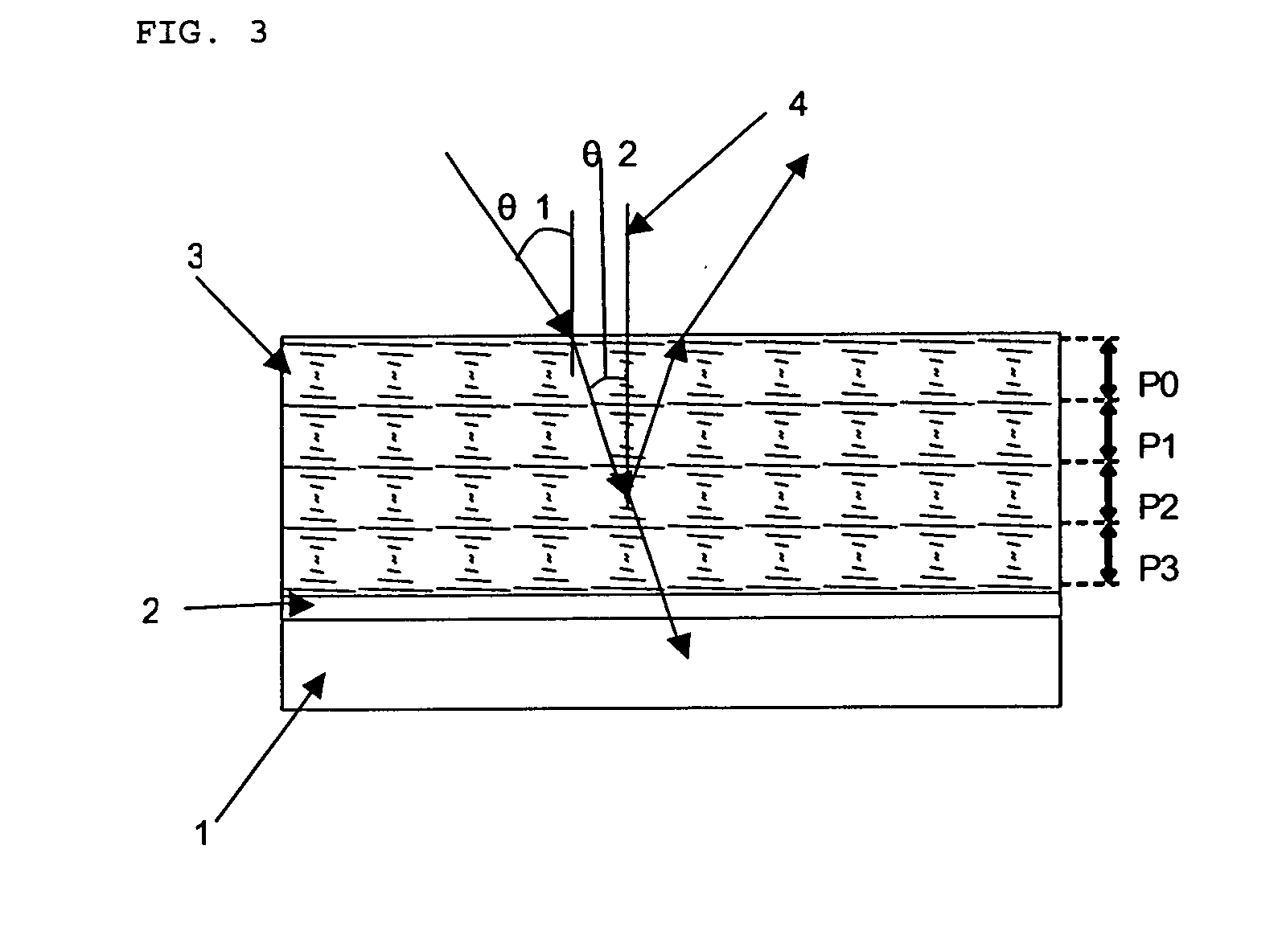
[0017]The optical element of the present invention has a cholesteric resin layer with chiral pitch of 400 nm or more and the maximum reflectivity in the selective reflection band at the incident angle of 0 degrees being 10% or more and 40% or less. In the cholesteric resin layer, as the incident angle is increased, the selective reflection band is shifted to the short-wavelength side, and if the optical element of the present invention is attached to a device having a light source, the color balance of blue, green and red when observed from an angle can be adjusted to the balance similar to the balance of blue, green and red when observed from the front. As a result, reddish or bluish display does not occur when observed from an angle, and color reproduction range can be widened.
[0018]In this specification, the terms “x or more” and “y or less” include their boundary values x and y. The wording “less than x” and “exceeding y” do not include the boundary values x and y. The boundary values x and v in a range indicated by “x to y” are included in the range.

Problems solved by technology

In general, even with the one that can invert a phase of light incident from an incident angle of 0 degrees (that is, the phase is retarded by a half wavelength), the phase of the light incident obliquely can not be retarded to exactly a half wavelength, which causes distortion.

Method used


Image

  • Optical Element, Polarizing Plate, Retardation Plate, Illuminating Device and Liquid Crystal Display
  • Optical Element, Polarizing Plate, Retardation Plate, Illuminating Device and Liquid Crystal Display
  • Optical Element, Polarizing Plate, Retardation Plate, Illuminating Device and Liquid Crystal Display

Examples


example 1

[0120]An optically isotropic film with a thickness of 100 μm (product name: “ZEONOR Film ZF14” by Zeon Corporation) made of a norbornene polymer was used as a transparent substrate. The both faces of the transparent substrate were plasma-treated so that wettability index became 56 dyne / cm. A composition for oriented film composed of 5 parts of polyvinyl alcohol and 95 parts of water was applied on one face of the transparent substrate and dried to form a film. Then, rubbing was performed with a felt roll in a direction in parallel with the longitudinal direction of the transparent substrate so as to obtain an oriented film with an average thickness of 0.1 μm.

[0121]100 parts of nematic liquid crystal compound (product name: “LC242” by Badische Anilin und Soda Fabrik), 3.60 parts of chiral agent (product name: “LC756” by Badische Anilin und Soda Fabrik), 3.21 parts of optical polymerization initiator (product name: “Irgacure907” by Ciba Specialty Chemicals Inc.) and 0.11 part of surfa...

example 2

[0128]An optically isotropic film with a thickness of 100 μm (product name: “ZEONOR Film ZF14” by Zeon Corporation) made of a norbornene polymer was used as a transparent substrate. The both faces of the transparent substrate were plasma-treated so that wettability index became 56 dyne / cm. A composition for oriented film composed of 5 parts of polyvinyl alcohol and 95 parts of water was applied on one face of the transparent substrate and dried to form a film. Then, rubbing was performed with a felt roll in a direction in parallel with the longitudinal direction of the transparent substrate so as to obtain an oriented film with an average thickness of 0.1 μm.

[0129]100 parts of nematic liquid crystal compound (product name: “LC242” by Badische Anilin und Soda Fabrik), 3.46 parts of chiral agent (product name: “LC756” by Badische Anilin und Soda Fabrik), 3.21 parts of optical polymerization initiator (product name: “Irgacure907” by Ciba Specialty Chemicals Inc.) and 0.11 part of surfa...


PUM

PropertyMeasurementUnit
wavelength bandaaaaaaaaaa
incident angleaaaaaaaaaa
transmittanceaaaaaaaaaa

Abstract

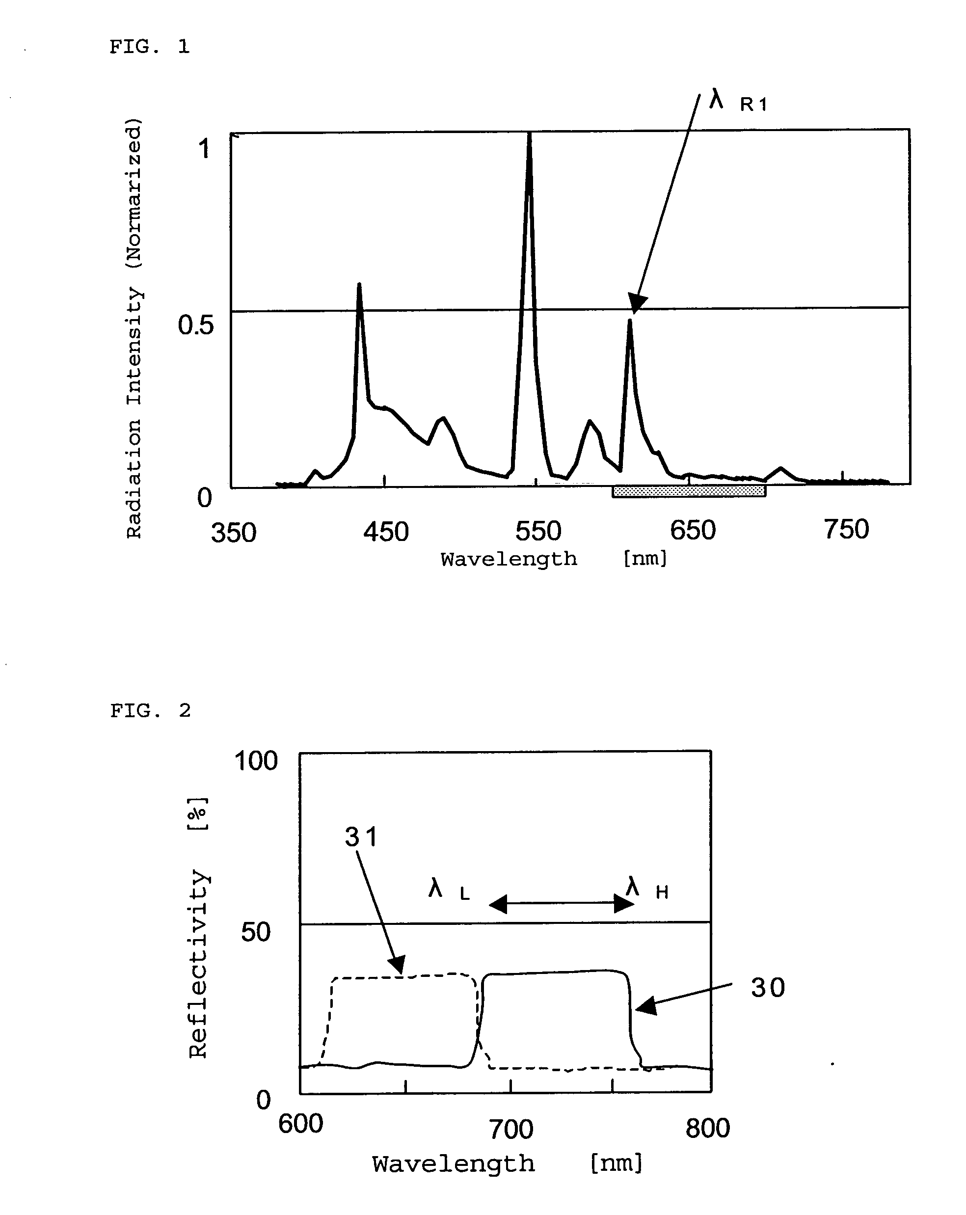
A polymerizable liquid crystal compound, a polymerization initiator, and a chiral agent, and a surfactant, orientation adjuster or the like as necessary are dissolved in a solvent to obtain a embrocation, the embrocation is laminated on an isotropic transparent film in a film state and dried, and the dried film is polymerized to give an optical element in which a lower limit λL of a band reflecting light at an incident angle of 0 degrees is longer than a wavelength λR1 of light indicating the maximum emission intensity in a wavelength band of 600 nm to 700 nm in the light emitted by a light source, and an average transmittance of the light with the wavelength 600 nm to 700 nm at the incident angle of 60 degrees is 40% or more and 90% or less.

Description

TECHNICAL FIELD[0001]The present invention relates to an optical element, a polarizing plate, a retardation plate, an illuminating device and a liquid crystal display. More specifically, the present invention relates to an optical element, a polarizing plate, a retardation plate, an illuminating device and a liquid crystal display used for displaying an image with well-balanced colors in observations similarly from the front and obliquely.BACKGROUND ART[0002]A liquid crystal display comprises a light source, two dichroic polarizers and a liquid crystal cell arranged between the dichroic polarizers. Light from a light source such as a cold cathode tube, a hot cathode tube and an LED (light emitting diode), and EL (electroluminescence) has blue light (wavelength 410 nm to 470 nm), green light (wavelength 520 nm to 580 nm) and red light (wavelength 600 nm to 660 nm) balanced to emit white light. The light is converted by the first dichroic polarizer to linear polarized light. The linea...

Claims


Application Information

Patent Timeline
Patent Type & Authority Applications(United States)
IPC IPC(8): G02F1/1335G02B5/00C09K19/02G02B27/28F21V13/12F21V9/14F21V9/40
CPCG02B5/3016G02B5/3083G02F2001/133541G02F1/133536G02F1/133533G02F1/133541G02F1/1335
Inventor ARAKAWA, KOHEIHORE, TOSHIHIKOOKUDE, SHUHEIHARAGUCHI, MANABU
Owner ZEON CORP
Why Eureka
Try Eureka