Signal receiving apparatus and method for wireless communication system using multiple antennas

signal receiving technology, applied in the field of signal receiving apparatus and method for a wireless communication system using multiple antennas, can solve the problems of large distortion of signals in the mobile communication environment, increase in the complexity of equalizers, delay spread, etc., and achieve the effect of reducing hardware complexity

Active Publication Date: 2010-06-03
ELECTRONICS & TELECOMM RES INST
View PDF3 Cites 40 Cited by
  • Summary
  • Abstract
  • Description
  • Claims
  • Application Information

AI Technical Summary

Benefits of technology

[0015]An embodiment of the present invention is directed to a receiving apparatus, which is capable of reducing complexity of hardware, and a receiving method thereof.

Problems solved by technology

In wireless communication channel environments, obstacles such as building cause multipaths, and the multipaths cause delay spread.
However, as the data rate increases, the complexity of the equalizer also increases.
However, the mobile communication environment greatly distorts signals due to multipath, shadow effect, propagation attenuation, interference, and the like.
Specifically, a fading phenomenon due to multipaths causes serious distortion of a signal given by combination of signals which have different magnitudes and phases through different paths.
Such a fading phenomenon is one of problems which must be solved in high-speed digital communications.
However, the MIMO system has a drawback in that it is vulnerable to ISI and frequency selective fading.
Although the IEEE 802.11n system provides a physical layer data rate of 300 Mbps, the throughput of 180 Mbps or higher may be difficult in theory.
However, this scheme is greatly affected by noise in a wireless communication system using multiple antennas.
If the noise distribution is differently generated among the multiple receiving paths, a more complex algorithm is required for detecting the transmit signals at the receiving end, and a larger amount of hardware resources are used.
However, this method must have complex hardware in order to calculate exact noise.
Furthermore, when hardware is made in a simple structure, its accuracy is lowered, resulting in the degradation of system performance.
Moreover, since a plurality of noise figures are not a time-varying function but is derived from a noise figure of an antenna and an analog device, the method which calculates a noise distribution at each time and reflects the calculated noise distribution may cause the performance degradation due to an estimation error.

Method used


Image

  • Signal receiving apparatus and method for wireless communication system using multiple antennas
  • Signal receiving apparatus and method for wireless communication system using multiple antennas
  • Signal receiving apparatus and method for wireless communication system using multiple antennas

Examples


Embodiment Construction

[0026]Exemplary embodiments of the present invention will be described below in more detail with reference to the accompanying drawings. The present invention may, however, be embodied in different forms and should not be constructed as limited to the embodiments set forth herein. Rather, these embodiments are provided so that this disclosure will be thorough and complete, and will fully convey the scope of the present invention to those skilled in the art. Throughout the disclosure, like reference numerals refer to like parts throughout the various figures and embodiments of the present invention. The drawings are not necessarily to scale and in some instances, proportions may have been exaggerated in order to clearly illustrate features of the embodiments.

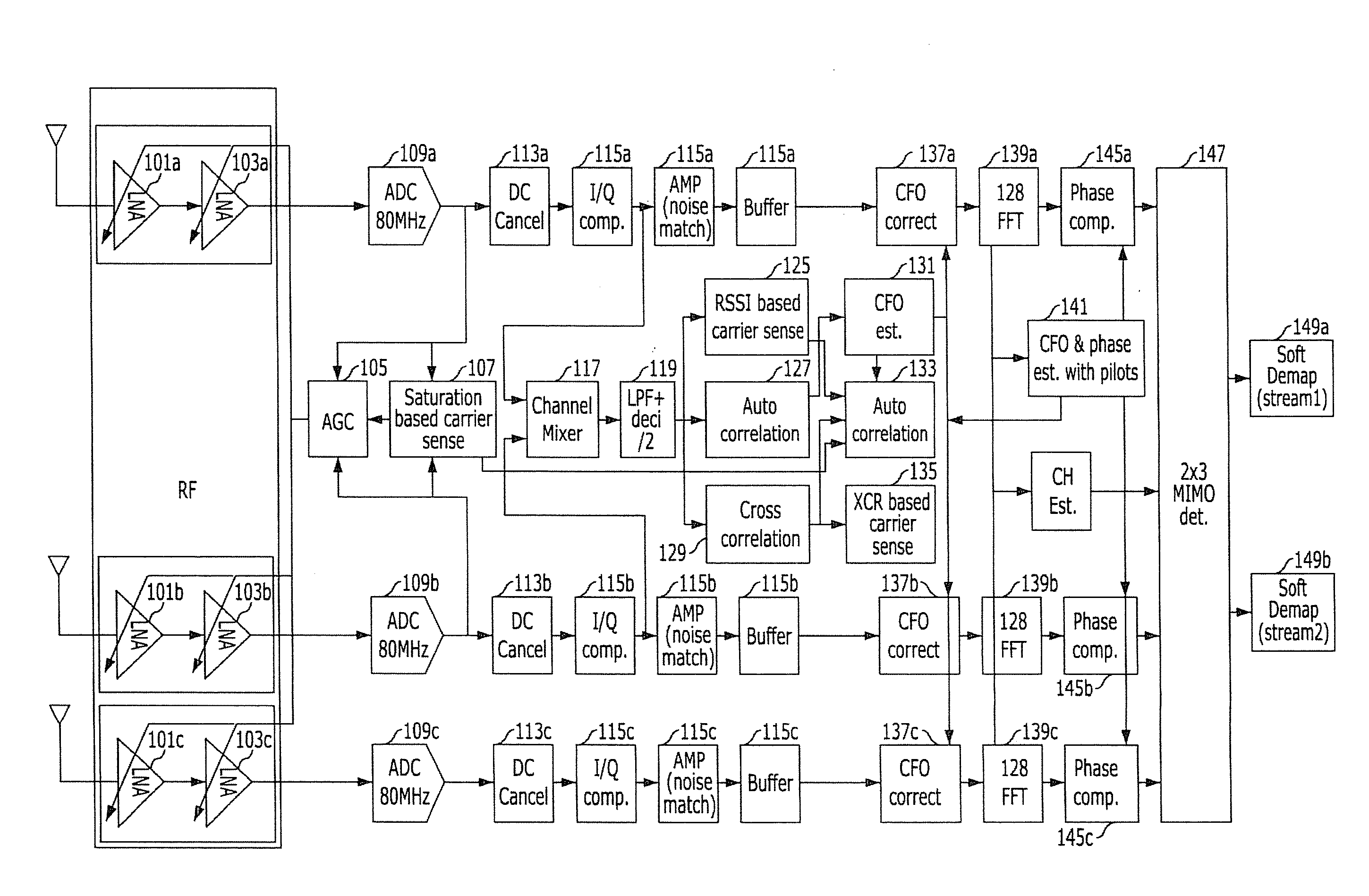
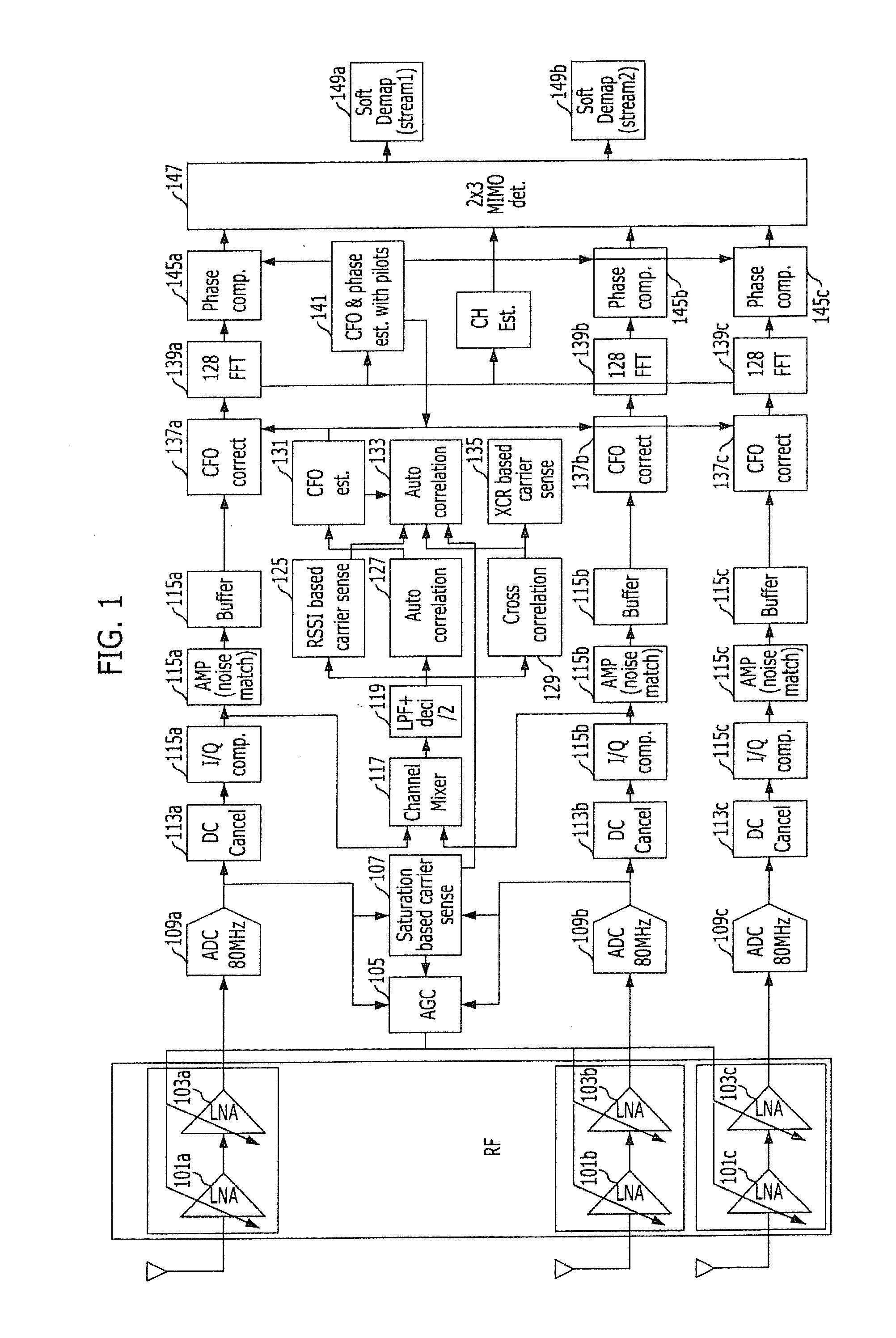
[0027]FIG. 1 illustrates an overall configuration of a receiver in accordance with an embodiment of the present invention.

[0028]Referring to FIG. 1, the receiver for receiving signals received through multiple antennas includes l...


PUM


Abstract

Provided are a receiving apparatus and method for a wireless communication system using multiple antennas. A receiving method for a wireless communication system using multiple paths, the receiving method comprising: receiving signals through a predetermined number of multiple paths; sensing a carrier according to saturation state degrees of the signals, and providing saturation state information; calculating automatic gain components of the received signals by using the received signals and the saturation state information of the received signals; and performing a noise matching process to amplify noises on the predetermined multiple paths according to the automatic gain components during a predetermined period.

Description

CROSS-REFERENCE(S) TO RELATED APPLICATIONS[0001]The present application claims priority of Korean Patent Application Nos. 10-2008-0121783 and 10-2009-0113950, filed on Dec. 3, 2008 and Nov. 24, 2009, respectively, which are incorporated herein by reference in their entirety.BACKGROUND OF THE INVENTION[0002]1. Field of the Invention[0003]Exemplary embodiments of the present invention relates to a signal receiving apparatus and method for a wireless communication system; and, more particularly, to a signal receiving apparatus and method for a wireless communication system using multiple antennas.[0004]2. Description of Related Art[0005]While the existing wireless communication systems have mainly provided voice services, the recent wireless communication systems increasingly tend to provide data services as well as voice services. In addition, the mainstream of data networks for providing data services has been cable-based data networks. However, many efforts to provide wireless servi...

Claims


Application Information

Patent Timeline
Patent Type & Authority Applications(United States)
IPC IPC(8): H04L27/00H04B1/10H04L27/08
CPCH04B1/1036H04L25/03038H04L25/03305H04L27/2647H04L27/2657H04L2025/03414H04L2025/0342H04L2025/03426H04L27/2655
Inventor LEE, IL-GUSON, JUNG-BOLEE, JE-HUNCHOI, EUN-YOUNGLEE, SOK-KYU
Owner ELECTRONICS & TELECOMM RES INST
Why Eureka
Try Eureka