Polymer film

a technology of polymer film and film film, applied in the field of polymer film, can solve the problems of low display quality and achieve the effects of low display quality, improved luminance, and negligible optical loss

Active Publication Date: 2010-06-03
MGC FILSHEET CO LTD +1
View PDF7 Cites 5 Cited by
  • Summary
  • Abstract
  • Description
  • Claims
  • Application Information

AI Technical Summary

Benefits of technology

[0015]As described above, with the conventionally proposed optical diffusion films, which are formed of binder resins and have resin particles dispersed therein, the display quality is low and the optical loss is not negligible. So far, no film having an embossed concaved and convexed surface for expressing an optical diffusion function provides, at the same time, an optical diffusion function, an improved luminance, a transmittance and the like which are of a sufficient level.
[0016]As a result of active studies performed in order to solve the above-described problems, the present inventor found that a polymer film having an Ra (arithmetic average roughness) of 0.5 μm to 2.5 μm, an Ry (maximum height) of 3 μm to 11 μm, an Rz (ten-point average height) of 3 μm to 8 μm and a light transmittance of 85% or higher provides, at the same time, an optical diffusion function, an improved luminance, a transmittance and the like, which are of a sufficient level not realized conventionally, and achieved the present invention. The present inventor also found that where Sm (average concave-concave / convex-convex interval) is 90 μm to 160 mm and the average inter-local peak interval (S) is 5 μm to 15 μm, an especially preferable performance is provided. The polymer film according to the present invention can be produced by melt extrusion.

Problems solved by technology

As described above, with the conventionally proposed optical diffusion films, which are formed of binder resins and have resin particles dispersed therein, the display quality is low and the optical loss is not negligible.

Method used


Image

  • Polymer film
  • Polymer film
  • Polymer film

Examples


example 1

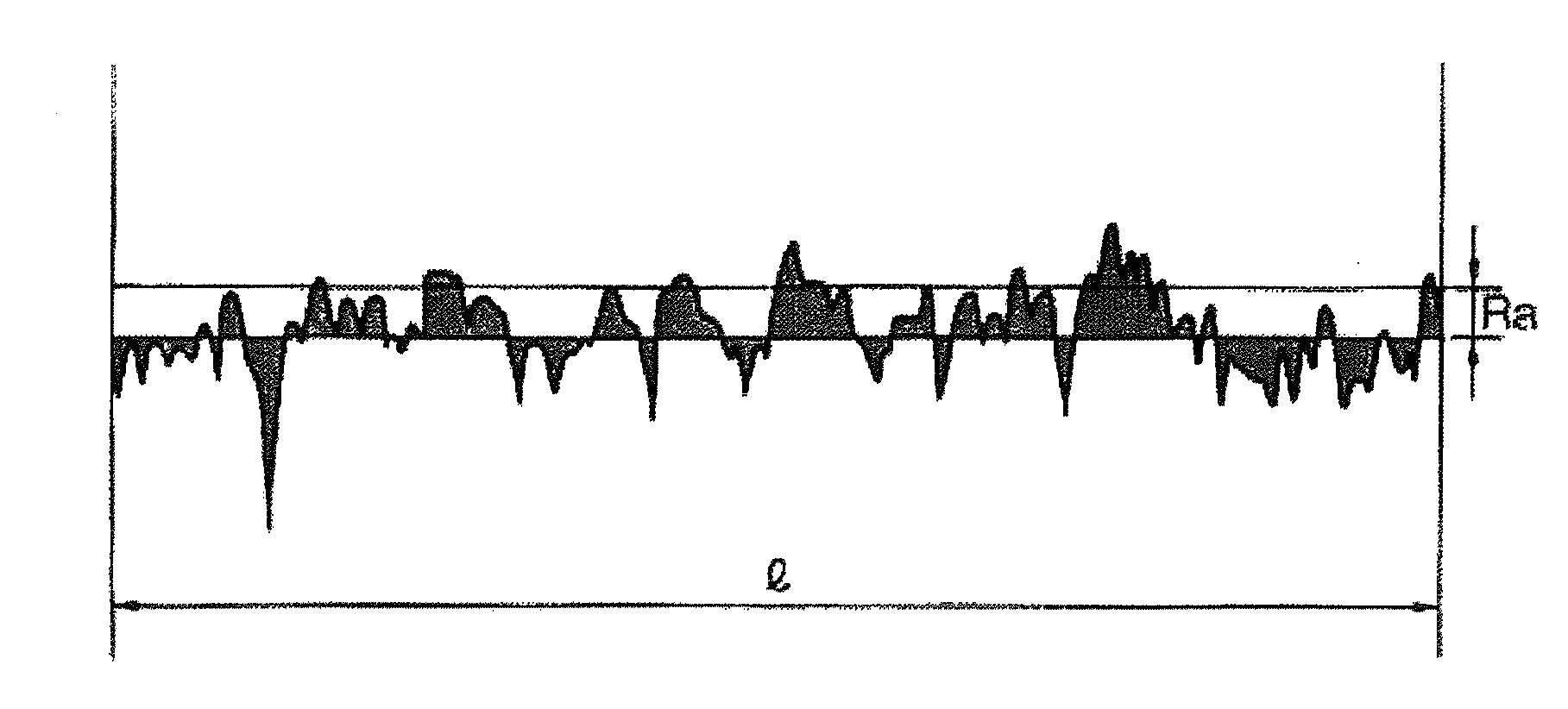
[0050]A pellet of a polycarbonate resin (Iupilon E-2000 produced by Mitsubishi Engineering-Plastics Corporation) was dried at 120° C. for 3 hours by a hot air drier. The resultant pellet was melt-extruded at 270° C. by a 90 mm monoaxial extruder and a T-die. The extruded melted film was nipped by a silicone rubber first cooling roll having a diameter of 220 mm and a metallic second cooling roll having a diameter of 450 mm and having an embossed surface with an arithmetic average roughness of 2.4 μm. Then, an emboss pattern was formed on a surface of the film. The film was cooled, and then passed through a metallic third cooling roll having a mirror surface. Thus, a film having a thickness of 130 μm with one surface being embossed was produced while being taken up by a take-up roll. In this procedure, the temperature of the first cooling roll was set to 50° C., the temperature of the second cooling roll was set to 130° C., and the temperature of the third cooling roll was set to 130°...

example 2

[0051]A pellet of a polycarbonate resin (Iupilon E-2000 produced by Mitsubishi Engineering-Plastics Corporation) was dried at 120° C. for 3 hours by a hot air drier. The resultant pellet was melt-extruded at 270° C. by a 90 mm monoaxial extruder and a T-die. The extruded melted film was nipped by a silicone rubber first cooling roll having a diameter of 220 mm and a metallic second cooling roll having a diameter of 450 mm and having an embossed surface with an arithmetic average roughness of 2.4 μm. Then, an emboss pattern was formed on a surface of the film. The film was cooled, and then passed through a metallic third cooling roll having a mirror surface. Thus, a film having a thickness of 75 μm with one surface being embossed was produced while being taken up by a take-up roll. In this procedure, the temperature of the first cooling roll was set to 60° C., the temperature of the second cooling roll was set to 135° C., and the temperature of the third cooling roll was set to 135° ...


PUM

PropertyMeasurementUnit
light transmittanceaaaaaaaaaa
height Rzaaaaaaaaaa
height Rzaaaaaaaaaa

Abstract

The present invention can provide a polymer film having an Ra (arithmetic average roughness) of 0.5 μm to 2.5 μm, an Ry (maximum height) of 3 μm to 11 μm, an Rz (ten-point average height) of 3 μm to 8 μm, and a light transmittance of 85% or higher. A preferable embodiment of the present invention can provide, at the same time, an optical diffusion function, an improved luminance, a transmittance and the like which are of a sufficient level not realized conventionally. In a still preferable embodiment, Sm (average concave-concave / convex-convex interval) of 90 μm to 160 μm and the average inter-local peak interval (S) is 5 μm to 15 μm.

Description

TECHNICAL FIELD[0001]The present invention relates to a polymer film usable for displays such as liquid crystal displays (LCDs) and in the field of optical devices. In more detail, the present invention relates to a film suitable to improve the luminance and the contrast of liquid crystal displays.BACKGROUND ART[0002]Conventionally, in display devices for, for example, displaying numerical figures or letters or performing planar light emission using point light sources such as light emitting diodes or linear light sources such as fluorescent lamps or cathode ray tubes, optical diffusion films are used which diffuse the transmitted light from the point or linear light sources to make the light appear to be from planar light sources.[0003]In the field of flat panel displays (FPDs), it is desired to alleviate the nonuniformity in the luminance and to improve the luminance in order to realize higher display performances.[0004]A general backlight unit of a liquid crystal display includes...

Claims


Application Information

Patent Timeline
Patent Type & Authority Applications(United States)
IPC IPC(8): B32B3/10B29C47/88B29C59/04B29K69/00B29L7/00B29L11/00C08J5/18F21V3/00F21V3/04G02F1/13357
CPCB29C59/04C08J5/18C08J2369/00Y10T428/24355G02B5/0278G02F1/133606G02B5/0221G02B1/11G02F1/1335
Inventor KATO, KENJIHAYASHI, KATSUSHIGEYOKOYAMA, JUN
Owner MGC FILSHEET CO LTD
Why Eureka
Try Eureka