
Pressure sensing method and system for flexible aerodynamic surfaces

a technology of aerodynamic performance and pressure sensing, which is applied in the direction of liquid/fluent solid measurement, volume measurement, volume measurement, etc., can solve the problems of real-time aerodynamic performance, inability to quantitatively measure the full scale, and the inability to quickly remove the bundle of enable signal wires, so as to achieve easy addition or removal of the sail without damage to the sail

Inactive Publication Date: 2010-06-03
SAILMETER
View PDF4 Cites 7 Cited by
  • Summary
  • Abstract
  • Description
  • Claims
  • Application Information

AI Technical Summary

Benefits of technology

[0009]The system according to the invention provides several features not present in the prior art, including that sensors are positioned on or within a batten, and are not directly secured to the sail. The batten can be easily added or removed from the sail without damage to the sail. A reference pressure plenum can be shared within the batten, between battens or between sails. Data from the battens can be transmitted wirelessly (a wired backup may also be used) to the accompanying software application and / or receiving system.
[0010]Given a number of sensors on the batten, an efficient means of organizing a network to connect the sensors should be used. Such a network should be capable of sending commands to the sensors, and returning the sensor data in an organized fashion to a master data-gathering node. In particular, it is advantageous for each sensor in the network to be identical, for the network to be self-organizing, and for the interconnecting hardware (wires, connectors, etc) to be minimized for robustness in a harsh environment.
[0011]An asymmetric daisy chain network provides a means of connecting a number of sensor nodes into a network, with a master data-gathering node. The network is asymmetric in that the uplink from the master to the sensor nodes is connected in series as a daisy chain, while the downlink is connected in parallel as a bus. This configuration allows the master node to initialize each sensor node in turn, assigning each sensor a number and a time-slot on the downlink bus. At the end of initialization, the master has a count of the number of sensors, and is able to broadcast commands to all enabled sensors simultaneously. Each slave sensor has a time-slot on the data bus to return its sensor data without collisions with the other sensors. This particular arrangement results in a simple interconnect, with a minimal number of wires.
[0012]Such a network arrangement provides several advantages, including:a) all of the sensors are functionally the same, in both hardware and software, thus there are no configuration devices such as ROMs, DIPswitches, or jumper-wires to preset;b) the interconnect between sensors is simple, requiring a minimal number of wires;c) the network is self-organizing. A simple initialization protocol assigns each sensor a number and a time-slot on the data bus, and gives the master a count of the number of sensors; andd) after initialization, the master is able to broadcast commands to all sensor nodes simultaneously. The sensor nodes are able to share the data bus using time-division multiplexing.

Problems solved by technology

A problem when measuring aerodynamic performance of surfaces such as sails is the inability to quantitatively measure the full scale, real-time aerodynamic performance.
A problem with this configuration is that as the number of sensors grows, the number of enable signals (and wires) grows as well.
For larger networks, the bundle of enable signal wires rapidly becomes undesirable.
An undesirable side effect of this preconfiguration is that it places a burden on the operator to ensure the network is configured correctly.
This requires significant overhead in terms of hardware and software to implement the protocol, and has significant power requirements.

Method used


Image

  • Pressure sensing method and system for flexible aerodynamic surfaces
  • Pressure sensing method and system for flexible aerodynamic surfaces
  • Pressure sensing method and system for flexible aerodynamic surfaces

Examples


Embodiment Construction

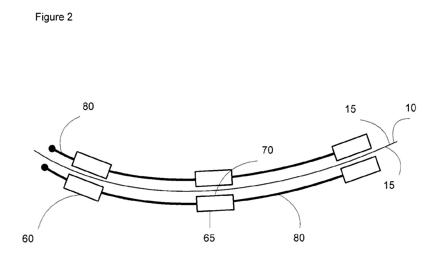
[0024]This system and method according to the invention enables full-scale real-time aerodynamic pressure to be measured on a flexible surface such as sail 10. The system comprises two main components: a plurality of sensors 20 with means to position the sensors, such as batten 30; and software related to managing, analyzing and displaying the measurements from sensors 20.

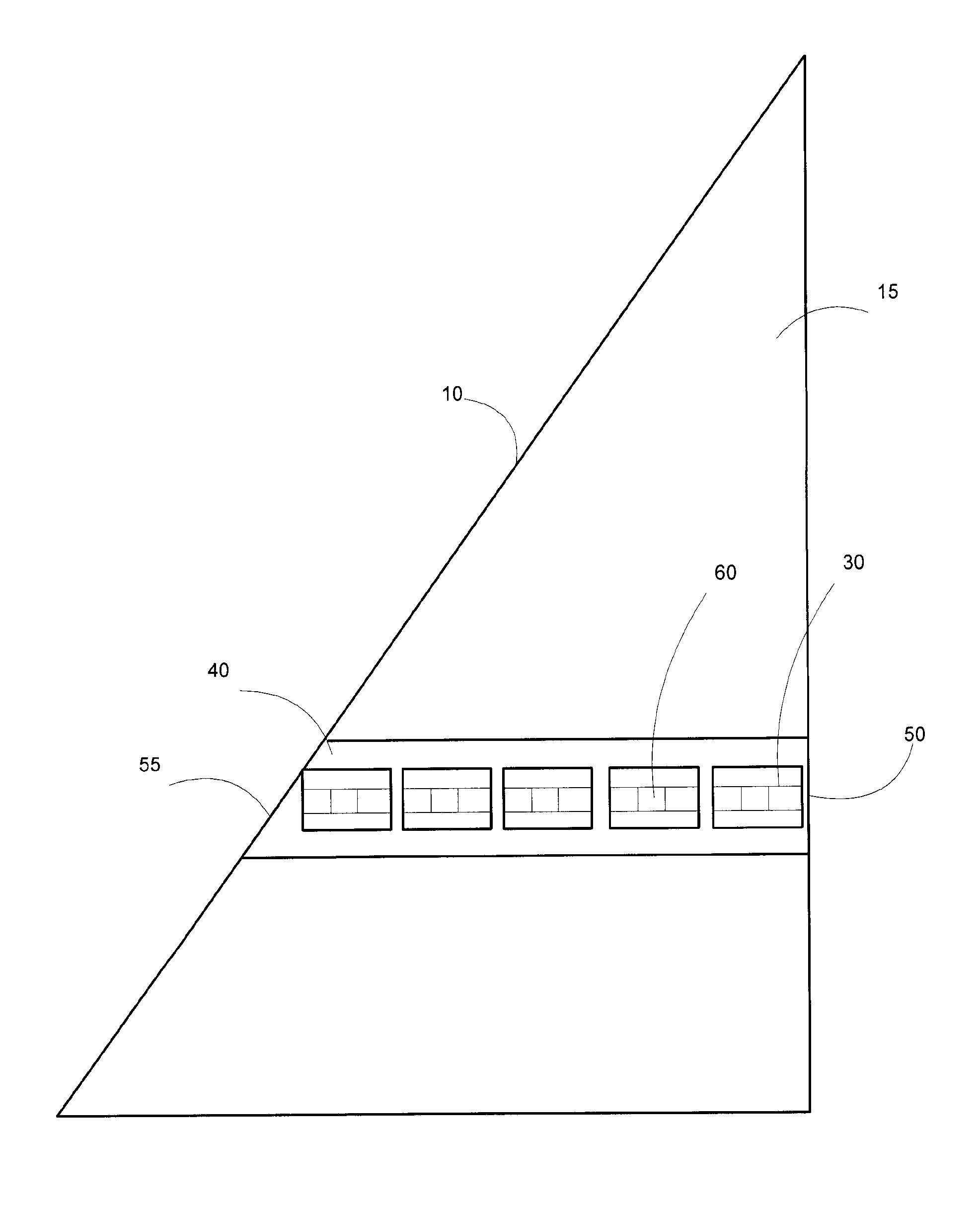
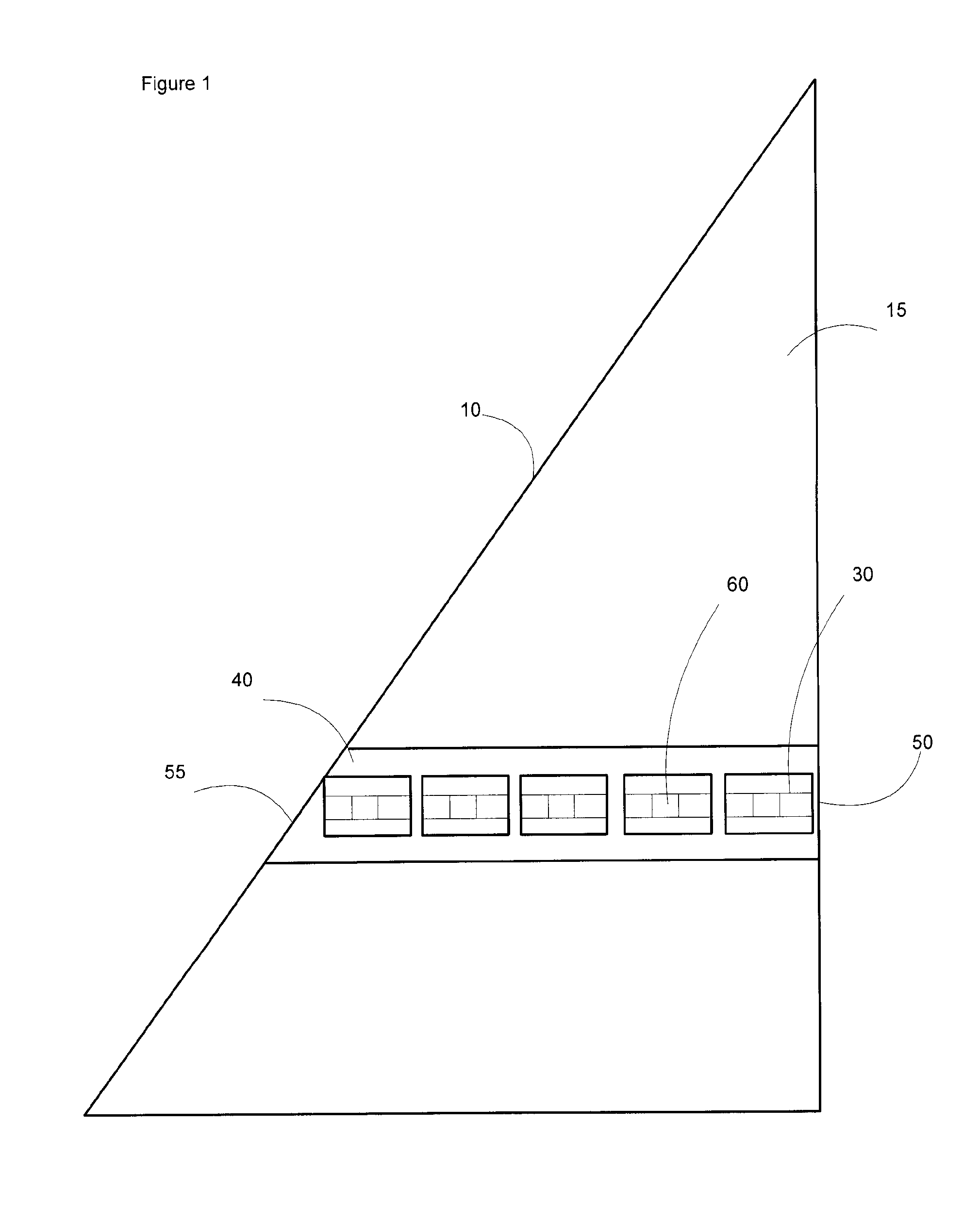
[0025]Batten 30 is a flexible tube like structure, which easily conforms to the shape of the surface 15 of sail 10, as seen in FIG. 1. Batten 30 may be made of plastics or composite materials. Batten can be attached to the surface 15 by means of a batten pocket 40, or tape or stitching in a similar manner as prior art battens. Batten pocket 40 may be a material sleeve sewn onto sail 10, which allows batten 30 to be easily slid into sail 10 and secured. Batten pocket 40 contains apertures for sensors 60 to be exposed to exterior pressure. Alternatively, the batten may be secured to the sail using tape or sewn direct...


PUM


Abstract

An apparatus for measuring aerodynamic performance is provided, including a batten; a plurality of pressure differential sensors positioned on the batten, each of the sensors having a first port for exposure to a first pressure and a second port for exposure to a second pressure; and a plenum positioned so that each of the first ports is exposed to a pressure within the plenum. The batten is positioned on a sail. The sensors may be in communication with a computer and the sensors may be networked in an asymmetric daisy chain network for uplink communications from the computer and networked in parallel as a bus for downlink communications to the computer.

Description

[0001]This application claims the benefit of U.S. Provisional Patent Application No. 60 / 909,882 filed Apr. 3, 2007, which is hereby incorporated by reference.FIELD OF THE INVENTION[0002]This invention relates to systems and methods of measuring aerodynamic performance of flexible surfaces such as sails, and more particularly to measuring aerodynamic performance using sensors.BACKGROUND OF THE INVENTION[0003]A problem when measuring aerodynamic performance of surfaces such as sails is the inability to quantitatively measure the full scale, real-time aerodynamic performance. Some prior art attempts to solve this problem include a differential pressure sensor and sail equipped with such a sensor as disclosed in FR2633717, and a sailboat and crew performance optimization system as disclosed in U.S. Pat. No. 6,308,649.[0004]FR2633717 discloses a sensor intended to measure the difference in pressure of two opposing sides of the sail of a ship or the like. The pressure difference is measur...

Claims


Application Information

Patent Timeline
IPC IPC(8): G01M9/06G01L13/00G01L7/00
CPCB63H9/0642G01M9/06B63H2009/065B63H9/065
Inventor GEORGE, DAVIDBURLEY, GREG
Owner SAILMETER
Learn More