Variable valve timing control apparatus for internal combustion engine

a timing control and internal combustion engine technology, applied in the direction of machines/engines, couplings, instruments, etc., can solve the problems of delayed release of locks and erroneously determined that the lock has been completed

Active Publication Date: 2010-06-10
DENSO CORP
View PDF4 Cites 32 Cited by
  • Summary
  • Abstract
  • Description
  • Claims
  • Application Information

AI Technical Summary

Benefits of technology

[0010]To achieve the objective of the present invention, there is also provided a variable valve timing control apparatus for an internal combustion engine that has a camshaft and a crankshaft, the variable valve timing control apparatus including a variable valve timing unit, a lock pin, a hydraulic control unit, and a lock release control unit. The variable valve timing unit is adapted to adjust valve timing by shifting a camshaft phase that is a rotational angular position of the camshaft relative to a rotational angular position of the crankshaft. The lock pin is movable in a lock direction for locking the camshaft phase at an intermediate lock phase that is generally middle of an adjustable range of the camshaft phase. The hydraulic control unit is adapted to control oil pressure that actuates the variable valve timing unit and the lock pin. Operation of the hydraulic control unit is changeable between a lock mode and a phase feed-back control mode. When the hydraulic control unit is operated in the lock mode, the lock pin locks the camsh

Problems solved by technology

As a result, in a case, where the camshaft phase erroneously stops at a certain phase slightly different from the intermediate lock phase due to some reasons (for example, a condition of oil temperature), it may be erroneously determined that the lock has been completed although the camshaft phase is not locked actually.
However, there may be a case, where the release of the lock is delayed due to some reasons (for example, frictional force between the lock pin and an inner periphery edge of the lock hole, or delay in the increase of oil pressure).

Method used


Image

  • Variable valve timing control apparatus for internal combustion engine
  • Variable valve timing control apparatus for internal combustion engine
  • Variable valve timing control apparatus for internal combustion engine

Examples


first embodiment

[0034]The first embodiment of the present invention will be described with reference to FIGS. 1 to 10.

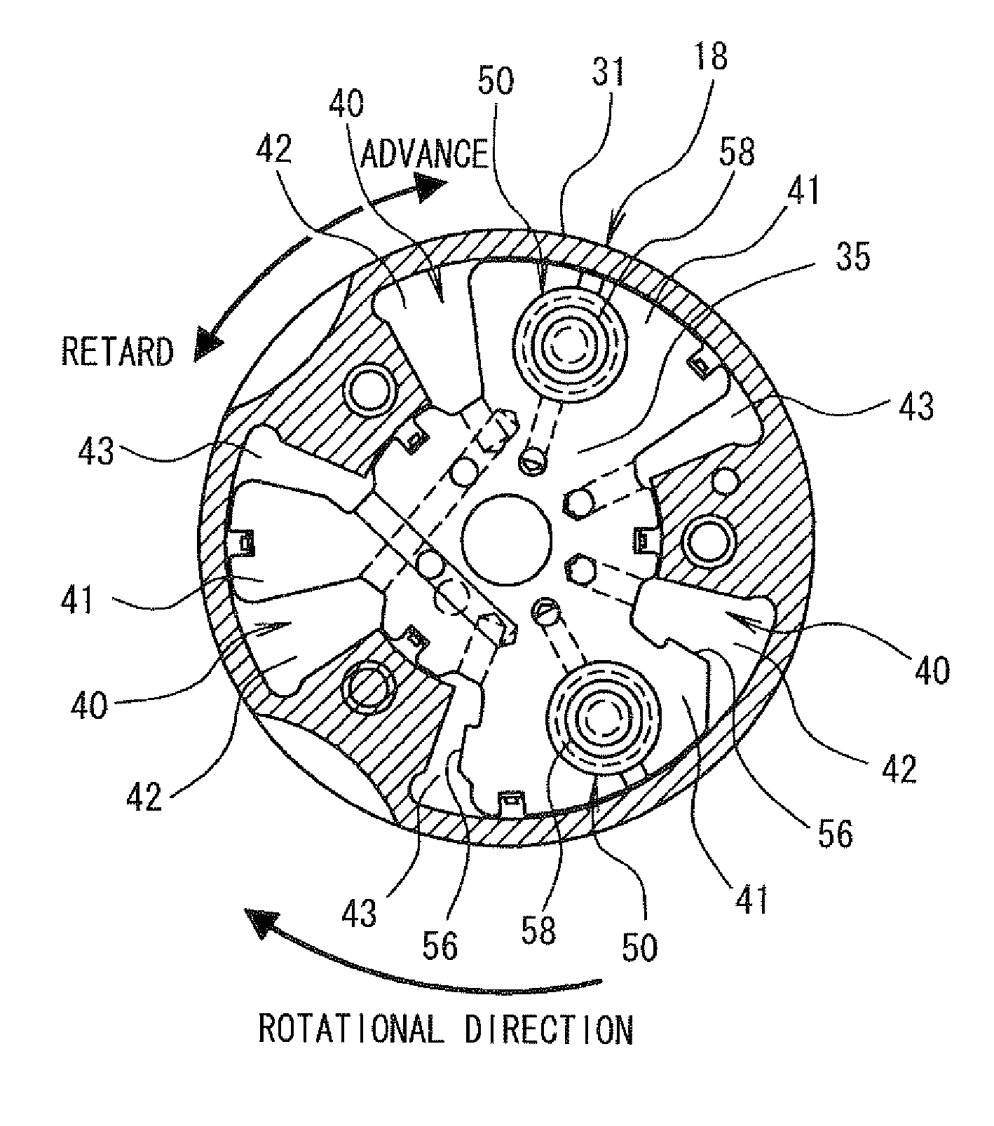
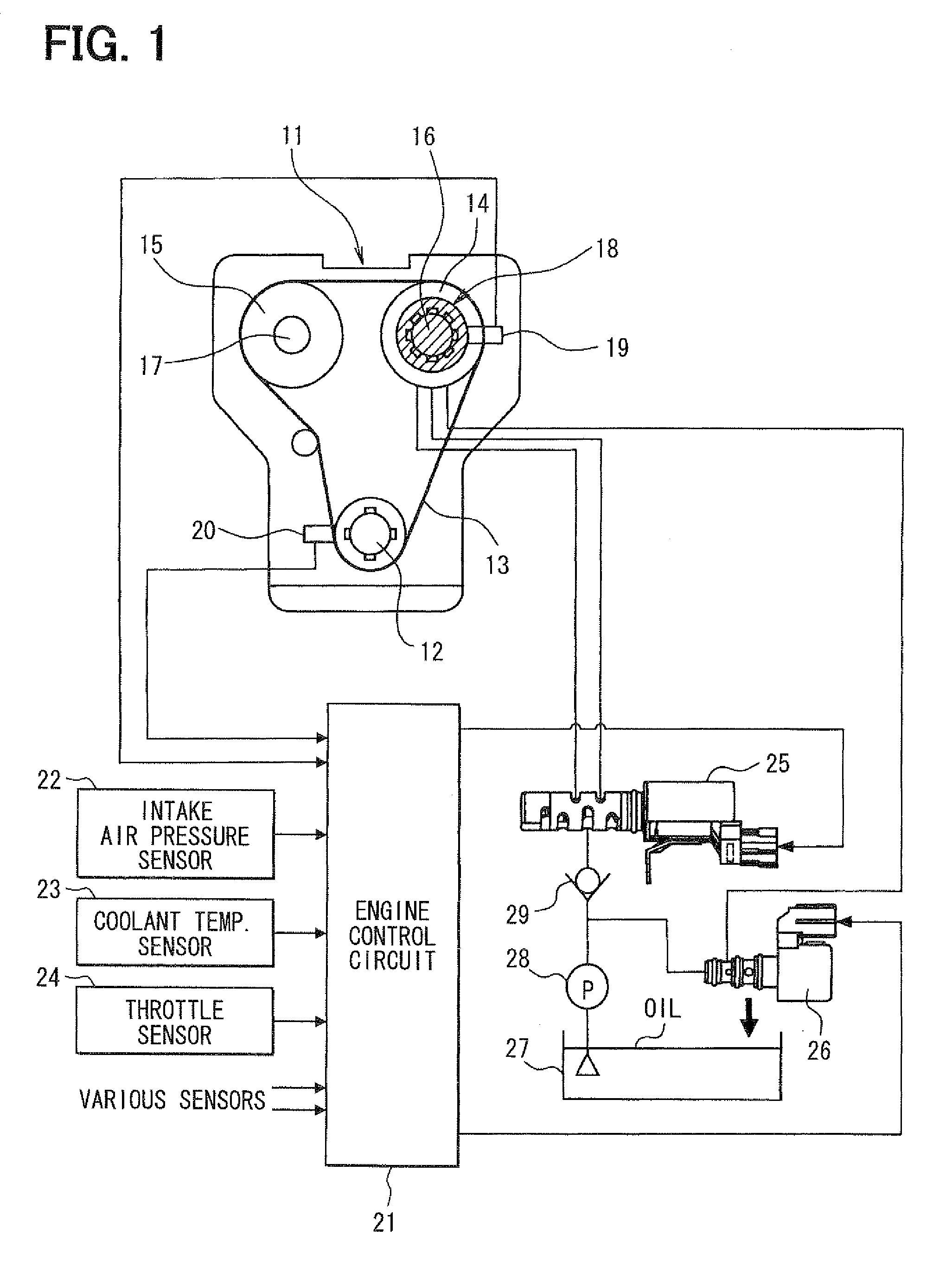
[0035]As shown in FIG. 1, an engine 11 (internal combustion engine) transmits drive force from a crankshaft 12 to an intake camshaft 16 and an exhaust camshaft 17 through a timing chain 13 and sprockets 14, 15. The intake camshaft 16 is provided with a variable valve timing unit 18 that adjusts an advance amount (or a camshaft phase) of the intake camshaft 16 relative to the crankshaft 12. More specifically, the camshaft phase is a rotational angular position of the intake camshaft 16 relative to a rotational angular position of the crankshaft 12.

[0036]Also, a cam angle sensor 19 is provided at a position radially outward of the intake camshaft 16 for outputting cam angle signal pulses at predetermined cam angles in order to identify cylinders. Also, a crank angle sensor 20 is provided at a position radially outward of the crankshaft 12 for outputting crank angle signal pulses at pr...

second embodiment

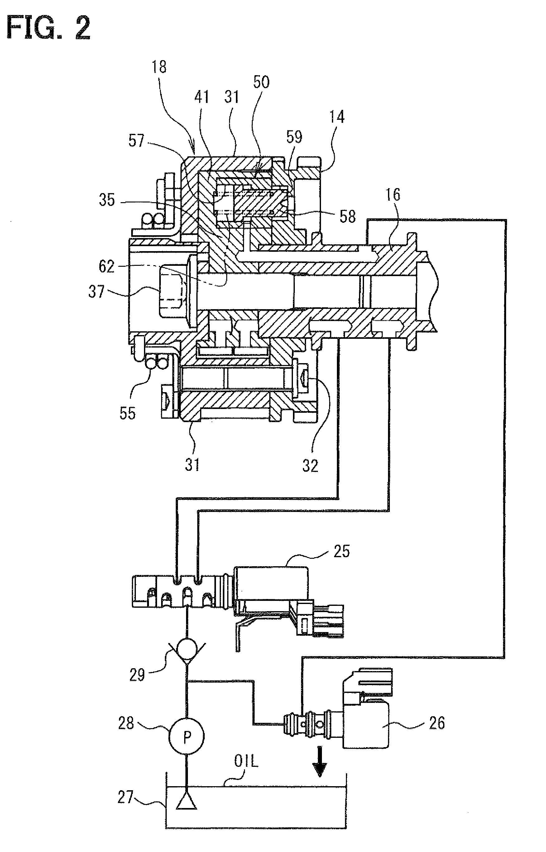
[0097]The above first embodiment illustrates a configuration that has the phase-control hydraulic control valve 25 and the lock-control hydraulic control valve 26, which are independent from each other. More specifically, the phase-control hydraulic control valve 25 independently controls oil pressure that actuates the variable valve timing unit 18, and the lock-control hydraulic control valve 26 independently controls oil pressure that actuates the lock pin 58. However, in the second embodiment shown in FIGS. 11 to 20, a hydraulic control valve 71 is singularly employed instead. More specifically, the hydraulic control valve 71 integrally has both (a) phase-control hydraulic control valve function for controlling oil pressure that actuates a variable valve timing unit 70 and (b) lock-control hydraulic control valve function for controlling oil pressure that actuates the lock pin 58.

[0098]A configuration of the variable valve timing unit 70 of the second embodiment is substantially ...


PUM


Abstract

A variable valve timing control apparatus for an engine includes a variable valve timing unit, a lock pin, a hydraulic control unit, and a lock control unit. The lock control unit causes the lock pin to lock the camshaft phase at an intermediate lock phase when a lock request is issued. When the lock request is issued, the camshaft phase is shifted in a reference direction to go beyond the intermediate lock phase while the lock pin is urged in a lock direction. When the camshaft phase stops around the intermediate lock phase, the lock control unit changes a control amount of the hydraulic control unit by a certain amount to shift the camshaft phase. The lock control unit determines that the camshaft phase has been locked at the intermediate lock phase when the camshaft phase is not shifted even after the lock control unit changes the control amount.

Description

CROSS REFERENCE TO RELATED APPLICATION[0001]This application is based on and incorporates herein by reference Japanese Patent Application No. 2008-312844 filed on Dec. 9, 2008.BACKGROUND OF THE INVENTION[0002]1. Field of the Invention[0003]The present invention relates to a variable valve timing control apparatus that adjusts valve timing of an internal combustion engine.[0004]2. Description of Related Art[0005]In a conventional hydraulic variable valve timing unit, as shown in JP-A-H9-324613 (corresponding to U.S. Pat. No. 5,738,056) and JP-A-2001-159330 (corresponding to U.S. Pat. No. 6,330,870), a lock phase during engine stop is set at a generally middle phase within an adjustable range of a camshaft phase such that the adjustable range of valve timing (camshaft phase) is enlarged. In the above conventional art, an intermediate lock phase, at which the phase is locked during the engine stop, is set at a phase suitable for starting the engine. The engine is started while the cams...

Claims


Application Information

Patent Timeline
IPC IPC(8): F01L1/34
CPCF01L1/022F01L1/3442F01L2001/0537F01L2001/34426F01L2001/3443F01L2820/02F01L2001/34469F01L2001/34483F01L2800/00F01L2800/03F01L2001/34463F01L2001/34466
Inventor TAKEMURA, YUICHI
Owner DENSO CORP
Why Eureka
Try Eureka