Ducted Fans with Flow Control Synthetic Jet Actuators and Methods for Ducted Fan Force and Moment Control

a technology of synthetic jet actuators and ducted fans, applied in the field of aerodynamics, can solve the problems of complex problem, net force in thrust direction, production of lift and pitching moment, etc., and achieve the effect of enhancing vehicle performance and efficiency and reducing undesirable moments

Inactive Publication Date: 2010-06-10
OHANIAN III OSGAR JOHN +4
View PDF9 Cites 50 Cited by
  • Summary
  • Abstract
  • Description
  • Claims
  • Application Information

AI Technical Summary

Benefits of technology

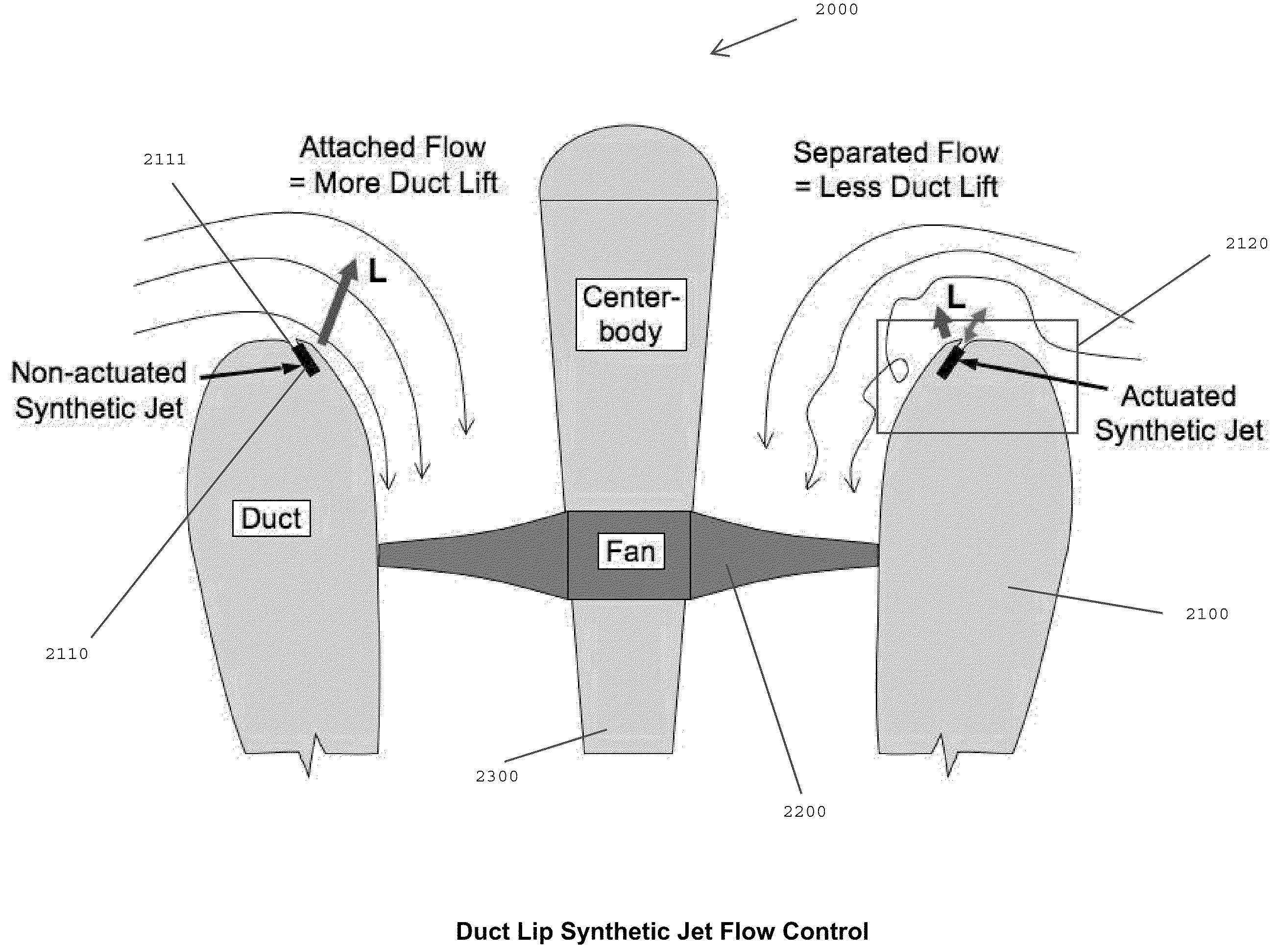
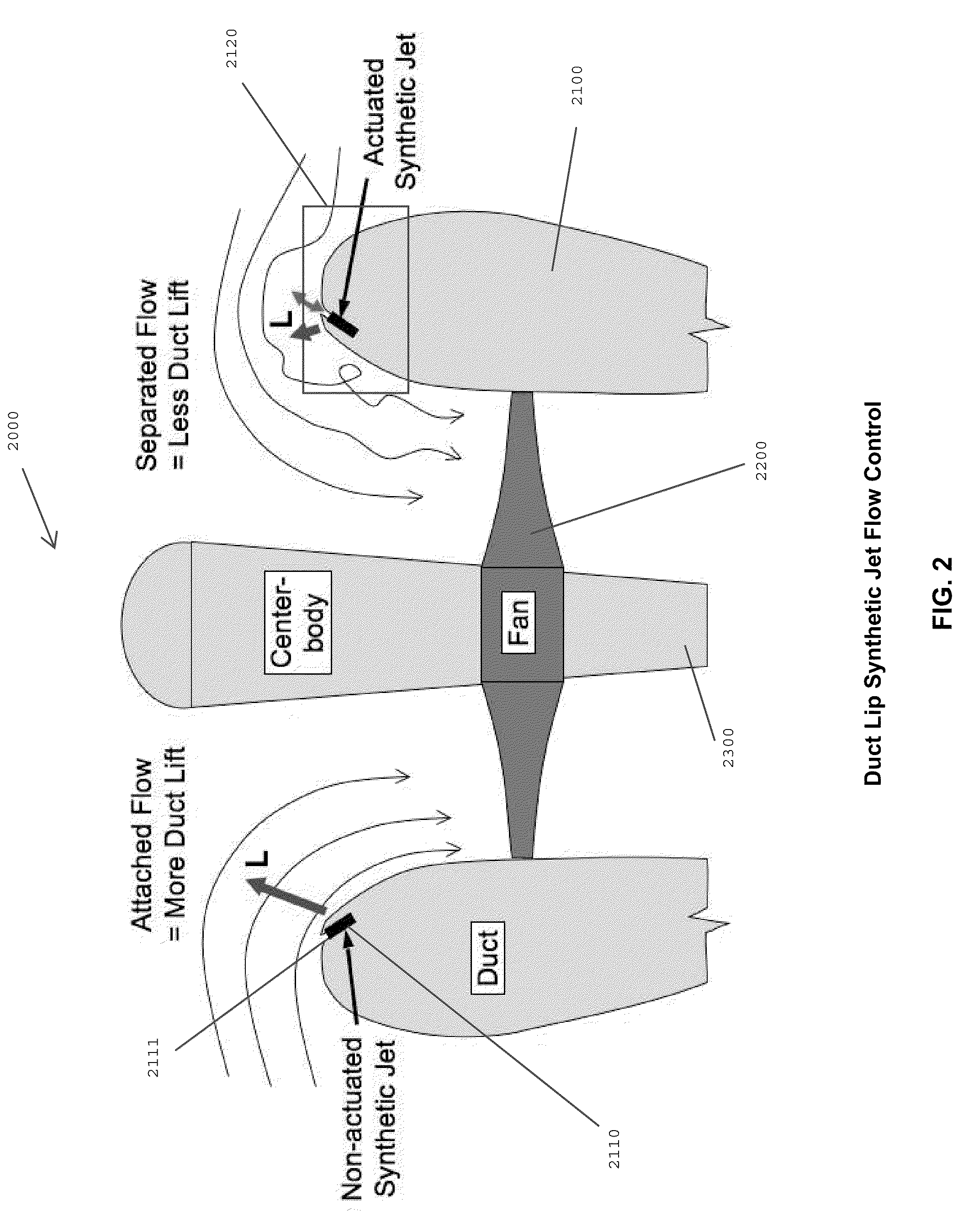
[0039]By controlling flow over a duct surface of a ducted-fan vehicle (for example, flow turned, accelerated, separation eliminated or produced on demand) the flight of a ducted-fan vehicle can be optimized. Such optimization can be useful during operation of the vehicle, for example, for combating gusting winds. In a particular application of an embodiment of the...

Problems solved by technology

It is a complex problem that depends on lip geometry, angle of attack, free stream velocity, and fan speed or rpm.
This phenomenon results in a net force in the thrust direction during hover and can produce lift and pitching moment in forward flight.
Depending on the sc...

Method used


Image

  • Ducted Fans with Flow Control Synthetic Jet Actuators and Methods for Ducted Fan Force and Moment Control
  • Ducted Fans with Flow Control Synthetic Jet Actuators and Methods for Ducted Fan Force and Moment Control
  • Ducted Fans with Flow Control Synthetic Jet Actuators and Methods for Ducted Fan Force and Moment Control

Examples


example i

Leading Edge Blowing Analysis

[0096]FIG. 8A-C provide a visual representation of a flow entering a ducted fan with respectively no blowing of jets, 100-ft / sec blowing, and 200-ft / sec blowing at the leading edge surface of a ducted fan. For these analyses, the blowing boundary condition was applied at the exit face of the slot. This reduced order modeling allowed for solution convergence. Comparing the 100-ft / sec and 200-ft / sec blowing with the no blowing case, FIGS. 8A-C show that leading-edge blowing separates the flow over the lip. When the blowing is not present, the flow proceeds into the duct smoothly. As blowing velocity is increased, the core of the separated region is lifted farther off the surface. Also, as blowing velocity is increased, the effect on the vehicle pitching moment is increased. The 50-ft / sec blowing velocity reduced the no blowing configuration pitching moment by more than a third, 100-ft / sec blowing reducing it by half, and 200-ft / sec blowing reducing the no-...

example ii

Coanda Trailing Edge Blowing Analysis

[0097]FIG. 9 shows a cross-sectional view of a duct, emphasizing trailing edge geometry of an embodiment of the invention. In this embodiment, a trailing edge geometry was developed for a 0.03 inch slot width and Coanda surface. In initial steadystate analyses, the jet velocity was imposed at the slot exit plane, i.e., the internal slot geometry was not modeled. In these cases, the internal orifice geometry was modeled with the sinusoidal velocity boundary condition applied at the beginning of the orifice neck. Steady blowing over the windward trailing edge at 200 ft / sec resulted in a normal force and decreased the pitching moment. Although the expansion of the streamtube resulted in an expected loss of thrust, power required by the fan also decreased.

[0098]Jet velocity was modeled as a time varying sinusoidal function. The 2400-Hz, ±200-ft / sec normal sinusoidal velocity boundary condition (values taken from bench test performance) was modeled ov...

example iii

Wind Tunnel Tests

[0101]Static (hover) tests were performed in a high bay area and wind tunnel tests were performed in the Virginia Tech 6 ft×6 ft Stability Wind Tunnel. The vehicle model was fabricated from machined aluminum and nylon as well as rapid prototyped resin parts. The model was supported by a 6-component force and moment balance in a side mount orientation to align the most sensitive channel of the balance with the vehicle's pitching moment axis (y-axis). Pitch sweeps were executed by rotating the wind tunnel turntable on which the balance is mounted, with the direction of flight in the positive x-direction (when angle of attack is zero).

[0102]FIG. 11 provides an illustration of the balance and vehicle used for the wind tunnel testing, along with the coordinate system used for collecting data. The data presented herein was transformed to move the moment reference center to the center of the duct lip as a simple datum for the vehicle design.

[0103]FIG. 12 illustrates this c...


PUM


Abstract

The present invention relates to the field of aerodynamics. More particularly, the present invention relates to manipulating air flow over a surface, such as the surface of a duct of a ducted fan vehicle. By controlling air flow over, at, or around the surface of a duct, the flight of the vehicle can be controlled. One embodiment of the invention provides a vertical take-off and landing (VTOL) ducted-fan vehicle comprising means for producing steady or unsteady blowing at a surface of a duct for producing control forces and moments for controlling flight. The means for unsteady blowing can be provided by synthetic jets and the means for steady blowing can be provided by a pressurized air supply. The synthetic jets can be integrated into the ducted-fan vehicles in numerous ways, including at the surface of the leading and/or trailing edge of the ducts. The synthetic jets can be independently operated to control the flight of the vehicle. A novel use of these inventive flow control concepts is to apply the control asymmetrically to the duct in order to produce an imbalance in forces, thus resulting in a moment or torque, which can be used to control flight.

Description

CROSS-REFERENCE TO RELATED APPLICATIONS[0001]This application relies on the disclosure and claims the benefit of the filing date of U.S. Provisional Application No. 61 / 110,689 filed Nov. 3, 2008, the disclosure of which is hereby incorporated by reference in its entirety.STATEMENT OF GOVERNMENT INTEREST[0002]This invention was made partially with U.S. Government support from the United States Air Force under SBIR Contract No. FA8651-07-C-0091. The U.S. Government has certain rights in the invention.BACKGROUND OF THE INVENTION[0003]1. Field of the Invention[0004]The present invention relates to the field of aerodynamics. More particularly, the present invention relates to manipulating air flow over a surface, such as the surface of a duct of a ducted-fan vehicle. By controlling air flow over, at, or around the surface of a duct, flight of a ducted-fan vehicle can be controlled.[0005]2. Description of Related Art[0006]Controlling flight of unmanned air vehicles (UAVs), and in particul...

Claims


Application Information

Patent Timeline
IPC IPC(8): B64C29/00
CPCB64C21/04B64C29/02B64C39/024Y02T50/166B64C2201/108B64C2201/162B64C2201/027Y02T50/10B64U10/13B64U30/20B64U50/14
Inventor OHANIAN, III, OSGAR JOHNKARNI, ETANLONDENBERG, WILLIAM KELLYGELHAUSEN, PAUL A.ENTSMINGER, ADAM LEE
Owner OHANIAN III OSGAR JOHN
Why Eureka
Try Eureka