Dissimilar material retention

Inactive Publication Date: 2010-06-10
CALDERA ENG
View PDF9 Cites 31 Cited by
  • Summary
  • Abstract
  • Description
  • Claims
  • Application Information

AI Technical Summary

Benefits of technology

[0008]In accordance with various aspects of the present invention, methods and apparatuses for designing and configuring dissimilar material retention, specifically a valve plug assembly, are disclosed. The methods and ap

Problems solved by technology

Sometimes, however, the materials involved and/or the environmental conditions will not permit the use of glue, adhesives, grout, mortar, solder, brazing, welding, notch/key methods, and similar techniques to adequately hold the assembled objects together.
However, there are various limitations and difficulties that accompany the use of an interference fit.
The ceramic plug head is then inserted into the metal plug head band, the metal cools and contracts, and an interference fit develops that causes the metal plug head band to grip the ceramic plug head.
Although highly useful, this technique is subject to several limitations and drawbacks.
For example, this approach involves a built-in limit on the upper serviceable temperature range for the valve when the materials have different coefficients of thermal expansion because if the operating temperature becomes high enough, the ceramic plug head may drop out of the expanded metal plug head band under service conditions and loading.
This maximum operating temperature can be raised by increasing the original interference fit, but doing so also has its own drawbacks.
The stresses in the hub and shaft will increase as the interference fit increases.
If the interference fit is too great, the hub and/or shaft itself may yield as the assembly cools and the ambient temperature interference is approached.
If the hub and/or shaft yields, then the required interference for oper

Method used


Image

  • Dissimilar material retention
  • Dissimilar material retention
  • Dissimilar material retention

Examples


Embodiment Construction

[0020]While exemplary embodiments are described herein in sufficient detail to enable those skilled in the art to practice the invention, it should be understood that other embodiments may be realized and that logical material and mechanical changes may be made without departing from the spirit and scope of the invention. Thus, the following detailed description is presented for purposes of illustration only.

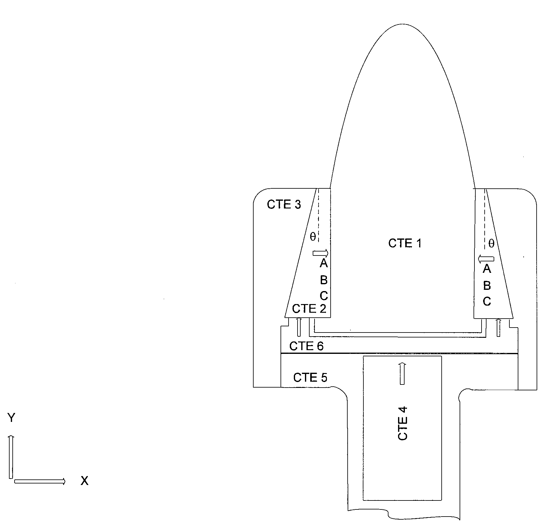
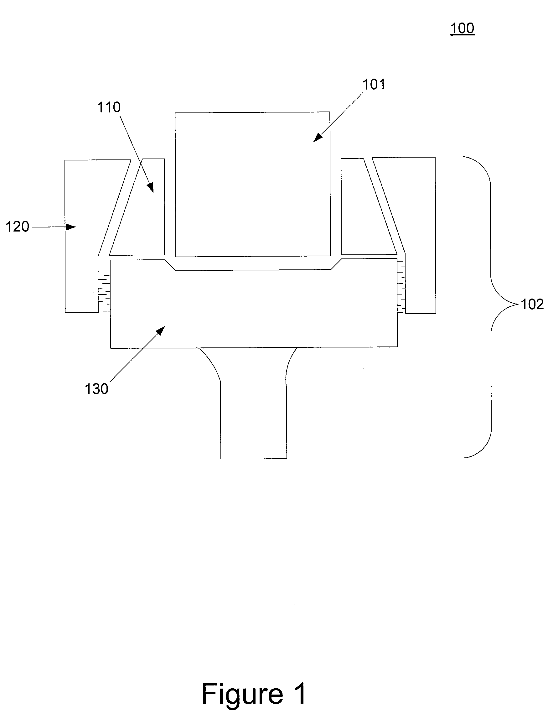
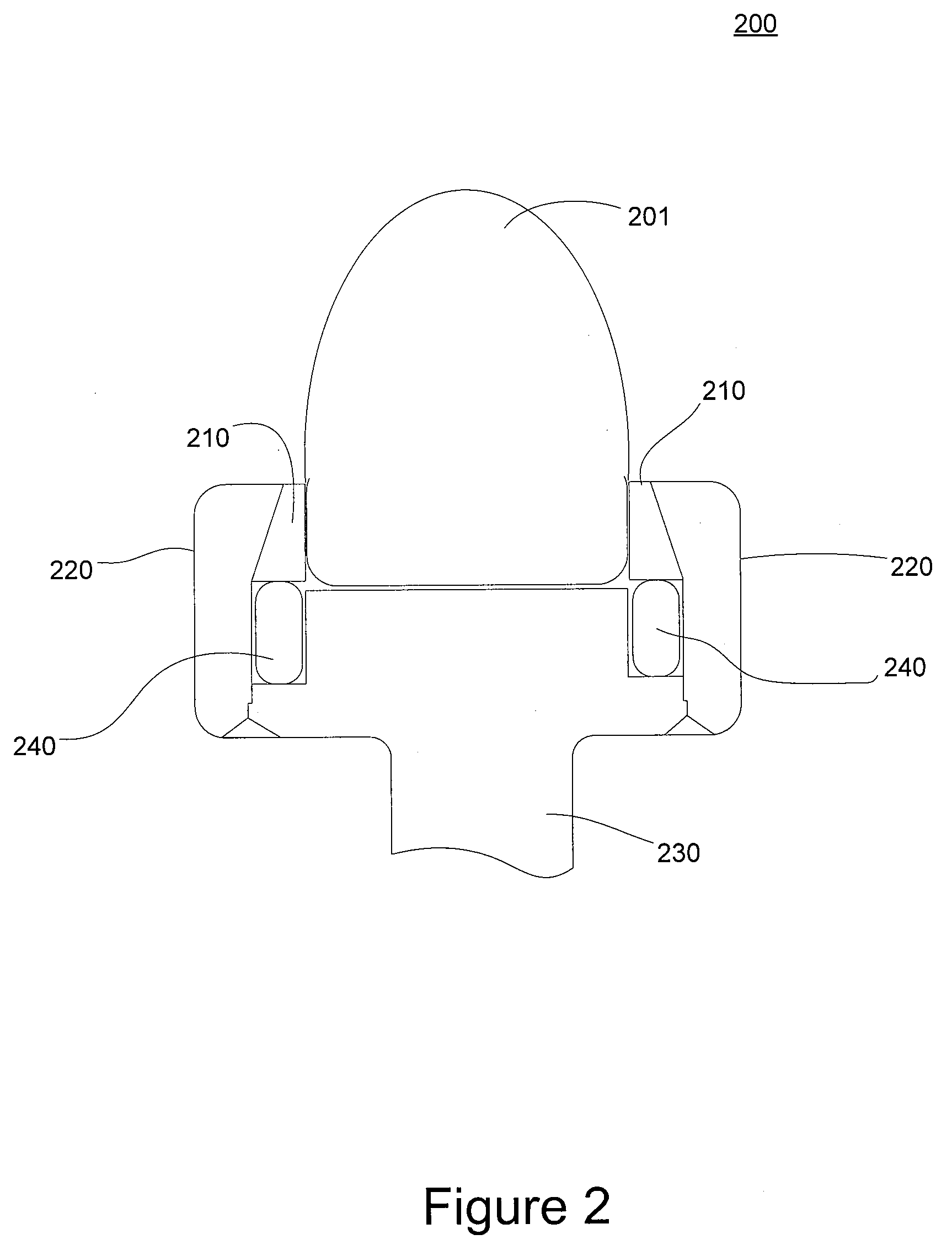
[0021]With reference now to FIGS. 1 and 2, in accordance with an exemplary embodiment of the present invention, an assembly 100 is formed by connecting a shaft 101 to a hub 102. In one exemplary embodiment, hub 102 comprises a base component 130, a collet 110, and a collet retainer 120. Although described herein in this manner, it should be appreciated that assembly 100 could also be described from the perspective of shaft 101 being connected to base component 130, wherein the shaft and base component are connected through use of collet 110 and collet retainer 120.

[0022]In an ex...


PUM

PropertyMeasurementUnit
Temperatureaaaaaaaaaa

Abstract

In accordance with various aspects of the present invention, methods and apparatuses for designing and configuring dissimilar material retention, specifically a valve plug assembly, are disclosed. The methods and apparatuses enable the application of a wider range of materials in a valve plug assembly than previous valve plug assemblies, and also increase the operational temperature range of the valve plug assembly. In an exemplary embodiment, a valve plug assembly comprises a plug head, a collet surrounding the plug head, a plug base adjacent to the collet, and a retainer surrounding the tapered outside surface of the collet and the plug base, where the plug head extends past the collet and the retainer. The valve plug assembly is configured to create an interference fit of the various components.

Description

BACKGROUND OF THE INVENTION[0001]Assemblies often are formed by joining two or more objects together. It is often very important that-those assemblies stay joined together throughout the service life of the assembly. Sometimes, however, the materials involved and / or the environmental conditions will not permit the use of glue, adhesives, grout, mortar, solder, brazing, welding, notch / key methods, and similar techniques to adequately hold the assembled objects together.[0002]In these circumstances, an interference fit may be a suitable assembly method to hold the objects together. However, there are various limitations and difficulties that accompany the use of an interference fit. As a specific example, in certain types of valves a ceramic plug head needs to be held firmly to one or more metal components of the valve. Typically, the plug head is retained within the metal component by way of an interference fit. For example, U.S. Pat. No. 6,685,167, (Robison et al.) describes one suc...

Claims


Application Information

Patent Timeline
IPC IPC(8): F16K25/00B21D51/16
CPCF16K1/38Y10T29/49426Y10T29/49412F16K25/005F16K1/48
Inventor ROBISON, JEFFREY C.
Owner CALDERA ENG
Why Eureka
Try Eureka