
Chip embedded printed circuit board and manufacturing method thereof

Inactive Publication Date: 2010-06-10
SAMSUNG ELECTRO MECHANICS CO LTD
View PDF5 Cites 24 Cited by
  • Summary
  • Abstract
  • Description
  • Claims
  • Application Information

AI Technical Summary

Benefits of technology

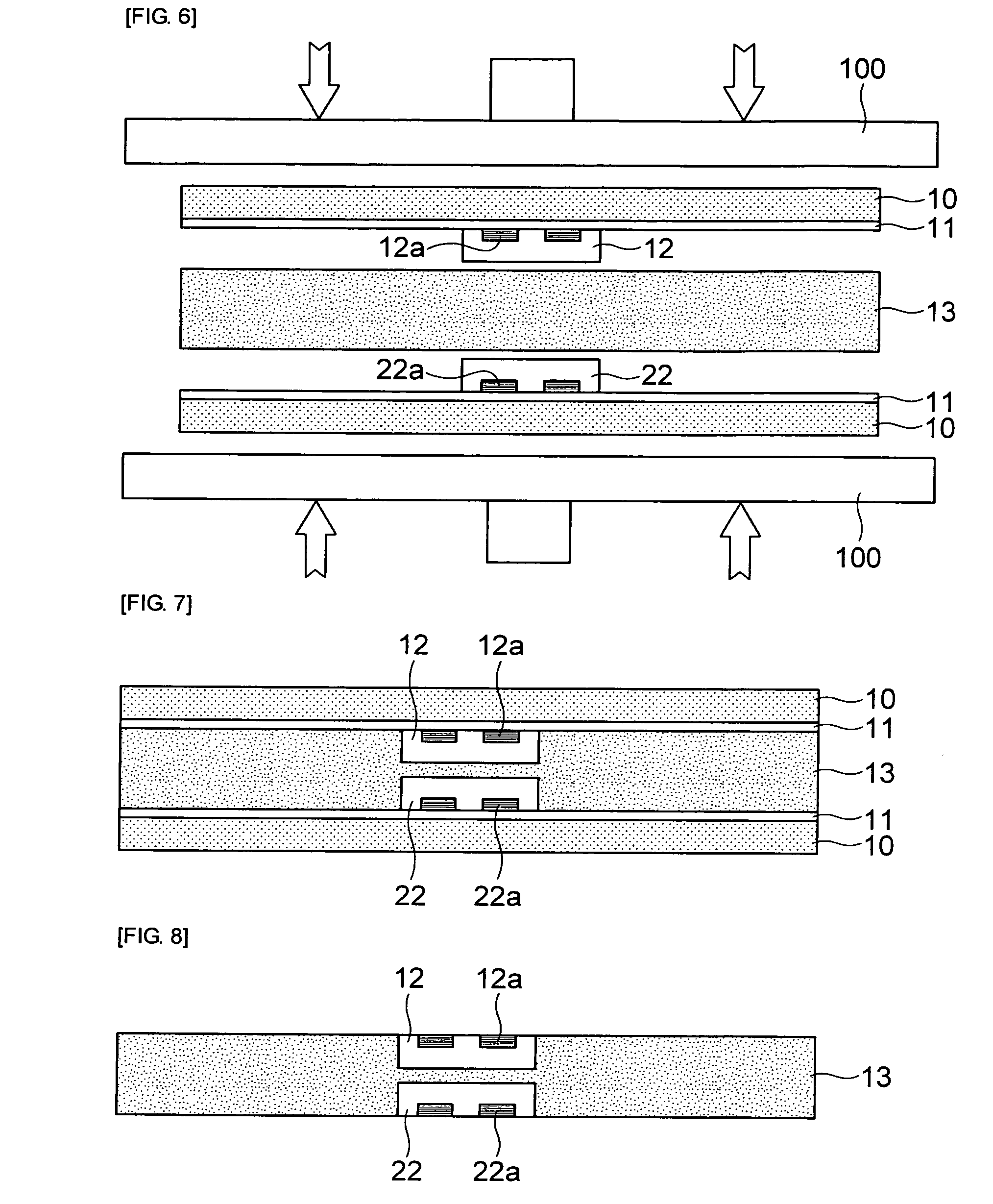
[0011]The present invention has been proposed in order to solve the above-described problems, and it is, therefore, an object of the present invention to provide a chip embedded printed circuit board and a manufacturing method thereof capable of reducing an entire thickness of a printed circuit board having a dual-chip embedded therein and improving yield and reliability of products by pressing a pair of the carrier plates on which the chips are mounted at upper and lower parts of an insulating layer to embed the dual-chip in the insulating layer.

Problems solved by technology

However, as described above, the conventional chip embedded printed circuit board in which the chip is embedded in the perforated core substrate by using the tape has a disadvantage that it is difficult to reduce an entire thickness of the substrate.
Also, as described above, in case of forming the via hole by the laser drilling method and the like, since it is difficult to form the via hole in an accurate position due to a position error of the chip or a tolerance of laser drilling and the like, there are problems such as deterioration of yield and reliability due to connection failure and the like.

Method used


Image

  • Chip embedded printed circuit board and manufacturing method thereof
  • Chip embedded printed circuit board and manufacturing method thereof
  • Chip embedded printed circuit board and manufacturing method thereof

Examples


Embodiment Construction

[0029]Reference will now be made in detail to the embodiments of the present general inventive concept, examples of which are illustrated in the accompanying drawings, wherein like reference numerals refer to like elements throughout. The embodiments are described below in order to explain the present general inventive concept by referring to the figures.

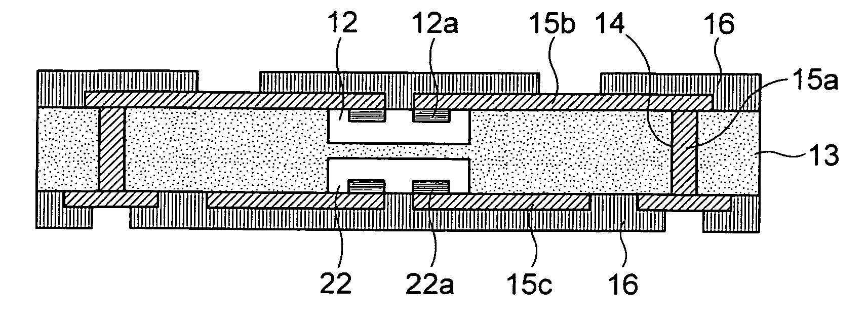
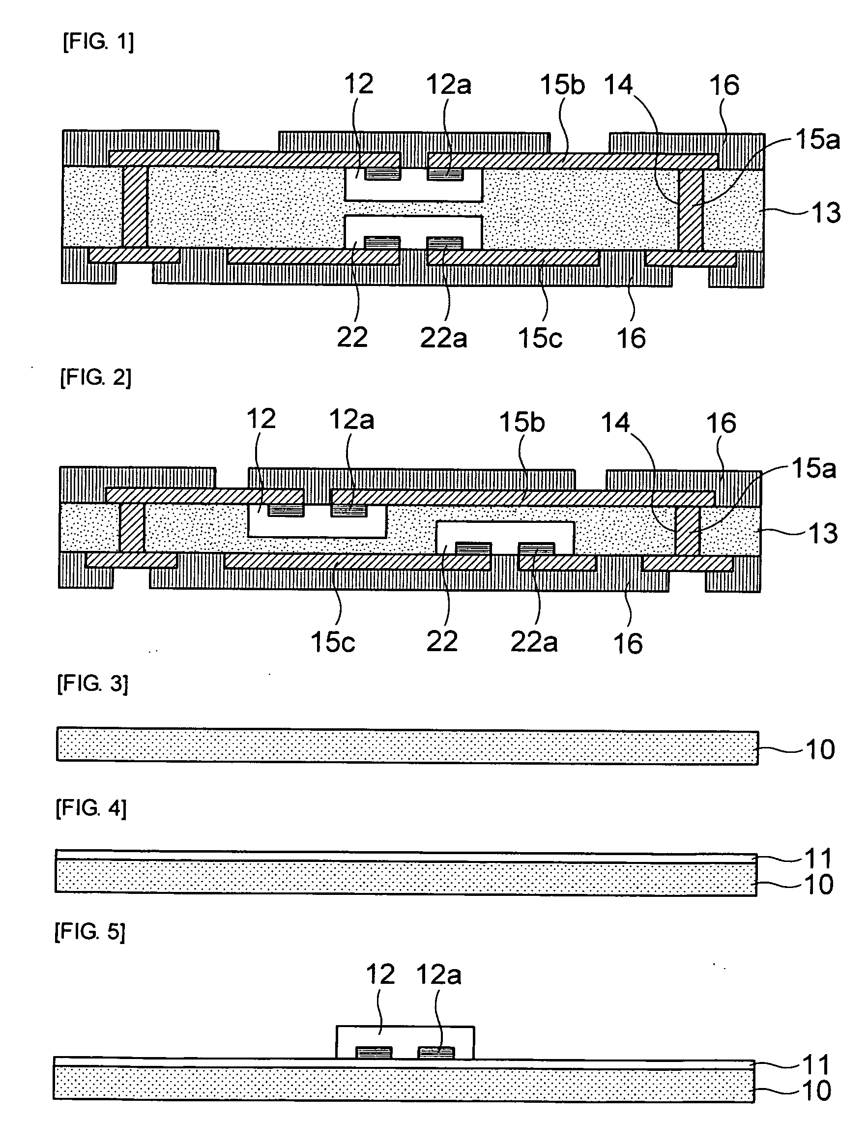
[0030]A chip embedded printed circuit board in accordance with an embodiment of the present invention will be described in detail with reference to FIGS. 1 and 2.

[0031]FIG. 1 is a cross-sectional view illustrating a structure of the chip embedded printed circuit board in accordance with the embodiment of the present invention, and FIG. 2 is a cross-sectional view illustrating another structure of the chip embedded printed circuit board in accordance with the embodiment of the present invention.

[0032]As shown in FIG. 1, the chip embedded printed circuit board in accordance with the embodiment of the present invention includes an insu...


PUM

PropertyMeasurementUnit
Adhesion strengthaaaaaaaaaa
aaaaaaaaaa

Abstract

The present invention relates to a chip embedded printed circuit board and a manufacturing method thereof and provides a chip embedded printed circuit board including: an insulating layer having vias formed therethrough; a first chip and a second chip embedded in the insulating layer and having pads, which are respectively exposed to upper and lower surfaces of the insulating layer, on one surfaces thereof; an upper pattern formed on the upper surface of the insulating layer to be connected to the pads of the first chip and the vias; and a lower pattern formed on the lower surface of the insulating layer to be connected to the pads of the second chip and the vias. Also, the present invention provides a manufacturing method of a chip embedded printed circuit board.

Description

CROSS-REFERENCE TO RELATED APPLICATIONS[0001]This application claims the benefit of Korean Patent Application No. 10-2008-0122914 filed with the Korea Intellectual Property Office on Dec. 5, 2008, the disclosure of which is incorporated herein by reference.BACKGROUND OF THE INVENTION[0002]1. Field of the Invention[0003]The present invention relates to a chip embedded printed circuit board and a manufacturing method thereof, and more particularly, to a chip embedded printed circuit board and a manufacturing method thereof capable of embedding a dual-chip in an insulating layer by pressing a pair of carrier plates on which the chips are mounted at upper and lower parts of the insulating layer.[0004]2. Description of the Related Art[0005]Recently, electronic components have been developed to achieve high density and high performance in response to demands for high performance and miniaturization of electronic devices. Therefore, a demand for a small printed circuit board capable of mou...

Claims


Application Information

Patent Timeline
IPC IPC(8): H05K1/18H05K3/30
CPCH01L21/6835Y10T29/49165H01L24/82H01L24/96H01L2224/18H01L2924/01029H01L2924/01059H01L2924/01078H05K1/185H05K3/426H05K2201/10515H05K2201/10674H05K2203/1461H01L2924/01006H01L2924/01033Y10T29/49146Y10T29/4913H01L24/18H01L21/568H01L24/19H01L2224/04105H05K1/18H05K3/40
Inventor KIM, HONG WONYI, SUNGJEONG, TAE SUNGKANG, JOON SEOK
Owner SAMSUNG ELECTRO MECHANICS CO LTD
Learn More