Grating based sensor combining label-free binding detection and fluoresnce amplification and readout system for sensor

a biochemical sensor and sensor technology, applied in the field of grating-based biochemical sensor devices and detection instruments, can solve problems such as inducing an unacceptable source of variation without proper control

Inactive Publication Date: 2010-06-10
X BODY
View PDF46 Cites 28 Cited by
  • Summary
  • Abstract
  • Description
  • Claims
  • Application Information

AI Technical Summary

Problems solved by technology

This practice, however, may induce an unacceptable source of variation without proper controls.

Method used


Image

  • Grating based sensor combining label-free binding detection and fluoresnce amplification and readout system for sensor
  • Grating based sensor combining label-free binding detection and fluoresnce amplification and readout system for sensor
  • Grating based sensor combining label-free binding detection and fluoresnce amplification and readout system for sensor

Examples


first embodiment

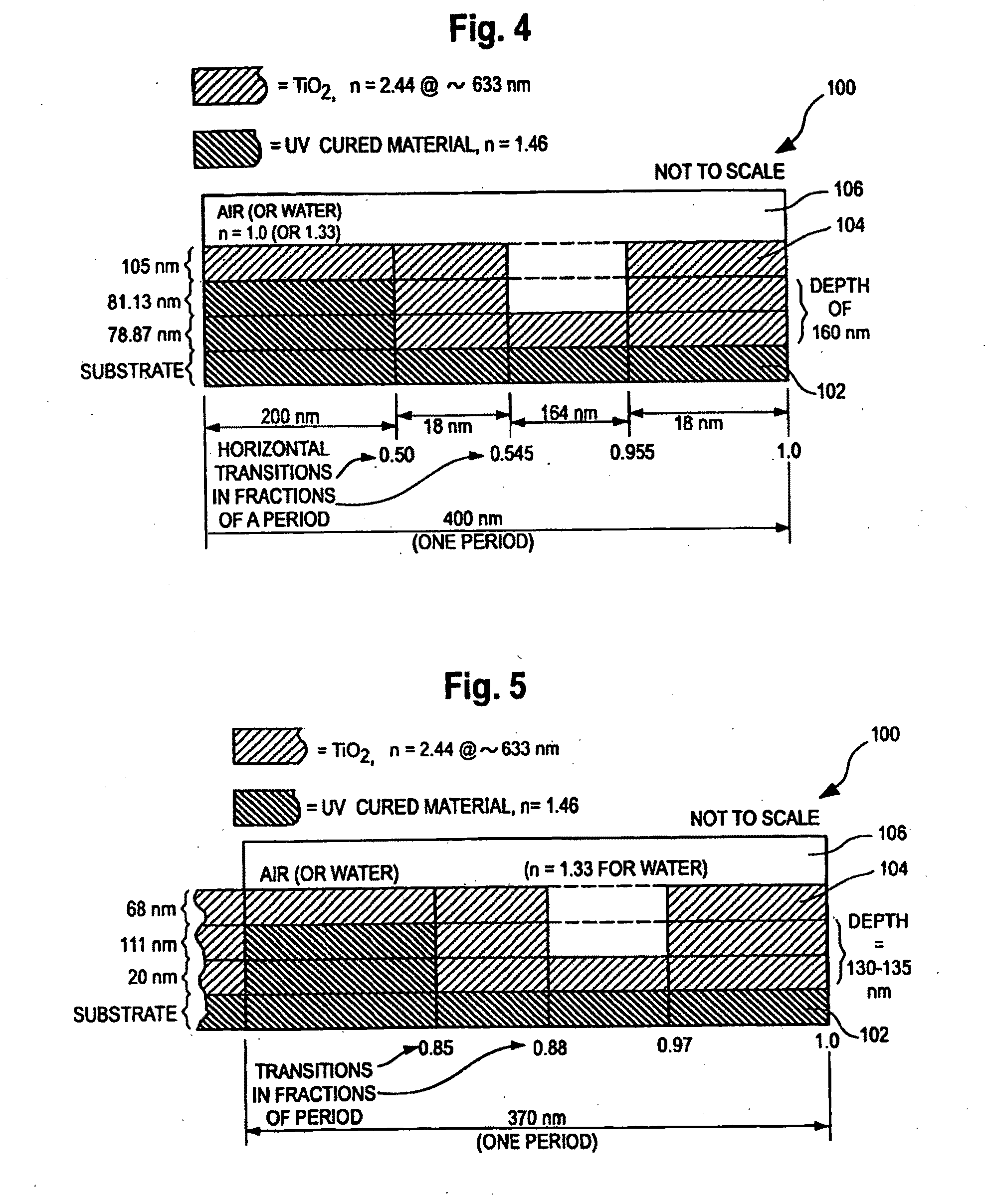
[0105]FIG. 4 is a schematic cross-sectional illustration of a first embodiment of a one-dimensional sensor having a grating structure 100 that is expected to meet commercial requirements for both ER and label-free applications of a grating-based sensor. FIG. 4 shows one period of a grating structure 100 in one dimension or direction. The dimensions are not to scale in FIG. 4.

[0106]The grating 100 of FIG. 4 is superimposed and bonded to a base sheet of clear material such as Polyethylene Terepthalate (PET) or other plastic, glass or other material (not shown).

[0107]The grating structure consists of a periodically repeating material 102 which preferably comprises a UV-cured material, e.g., epoxy, applied with the aid of a grating master wafer (not shown) to replicate the grating pattern onto the base sheet of PET material located below the layer “substrate.” The UV cured material 102 is applied to a substrate sheet such as PET. Substrate materials can also include polycarbonate or cyc...

second embodiment

[0116]FIG. 5 is a cross-section of a second embodiment, showing one period of the grating structure in one dimension and the structure of the of the UV cured layer 102, the high index of refraction layer 104, and the sample medium 106. The dimensions and transition points are as shown in the drawing. The drawing is not to scale.

[0117]The design of FIG. 5 differs from that of FIG. 4 is several respects:

[0118]a) It has a shorter grating period.

[0119]b) It has narrower grating troughs or recesses. The “duty cycle” (percentage of the grating at the upper level in a unit cell) is 88% in FIG. 5 (0 to 0.85 and 0.97 to 1.0). Narrow troughs with duty cycles of between 70 and 95% are exemplary of the narrow trough embodiments. The narrow troughs generally give better label-free detection results. The narrow trough feature narrows the TE resonance peak, thus indicating increased field strength. While practical use of the ER effect requires a sufficiently broad resonance, a resonance with exces...


PUM

PropertyMeasurementUnit
molecular weightaaaaaaaaaa
molecular weightsaaaaaaaaaa

Abstract

A grating-based sensor is disclosed that has a grating structure constructed and designed for both evanescent resonance (ER) fluorescence detection and label-free detection applications. One and two-dimensional gratings are also disclosed, including gratings characterized by unit cells with central posts, central holes, and two-level, two-dimensional gratings. A readout system for such sensors is also disclosed. Various applications for the biosensors are described, including cell-based assays for assessing the effect of drug compounds, proteins, peptides and other materials on cell function. A biosensor embodiment optimized for a luminescent response at two different wavelengths is also described. Such luminescent response could be produced by fluorescence (either native or from an attached fluorophore), phosphorescence, chemi-luminescence, or other luminescence technology. Two different luminescence technologies could be combined on the same biosensor chip.

Description

PRIORITY[0001]This application claims priority to U.S. patent application Ser. No. 11 / 818,742 filed Jun. 15, 2007, the content of which is incorporated by reference herein.BACKGROUND[0002]A. Field of the Invention[0003]This invention relates generally to grating-based biochemical sensor devices and detection instruments for such devices. Grating-based sensors are typically used for optical detection of the adsorption of a biological material, such as DNA, protein, viruses or cells, small molecules, or chemicals, onto a surface of the device or within a volume of the device. The sensor of this invention has a grating structure that is constructed in a manner for use in two different applications: (a) label-free binding detection, and (b) fluorescence detection, for example wherein the sample is bound to a fluorophore or emits native fluorescence.[0004]B. Description of Related Art[0005]1. Label-Free Detection Sensors[0006]Grating-based sensors represent a new class of optical devices...

Claims


Application Information

Patent Timeline
Patent Type & Authority Applications(United States)
IPC IPC(8): C12Q1/02C12M1/34
CPCG01N21/6452G01N21/648G01N33/6872G01N21/7743G01N33/54373G01N21/76Y10S436/805
Inventor CUNNINGHAM, BRIAN TLI, PETER Y.LAING, LANCE G.JOGIKALMATH, GANGADHARBINDER, BRANT
Owner X BODY
Why Eureka
Try Eureka