Grinding holder in a machining device

a technology for grinding holder and machining device, which is applied in the direction of grinding head, manufacturing tools, other manufacturing equipment/tools, etc., can solve the problems of hardening or stiffening of the flexible cord, deterioration of the flexibility of the grinding holder between the machine and the tool, and worsening the machining and the resulting plane and flatness, etc., to achieve more precise performance, easy control of the grinding holder, and the effect of easy adjustmen

Active Publication Date: 2010-06-10
HUSQVARNA AB
View PDF9 Cites 2 Cited by
  • Summary
  • Abstract
  • Description
  • Claims
  • Application Information

AI Technical Summary

Benefits of technology

[0019]Providing a machine for machining floor or road surfaces with a grinding holder according to the invention for a tool holder and a tool used in the machine, which grinding holder has an adjustable adaptability for the tool makes the tool more easily controlled during machining and provides the tool with a more exact performance when machining. This also means that the suspension of the tool holder and the tool and associated components may be optimized compared to prior art grinding holders, and that the grinding holder according to the invention enables an adjustability in that it may be equipped with any suitable flexibility/dampening, i.e. any suitable stiffening or softening of the tools adaptability, by only replacing the present at least one flexible/elastic element with another element having other properties, shape or size

Problems solved by technology

A disadvantage of the known grinding holders for tool holders in machines for machining surfaces, e.g. floor surfaces, is that the flexible cord is hardened or stiffened and compressed over time and wears, whereby the flexibility in the grinding holder between the machine and the tool deteriorates over time and worsens the machining and the resulting planes and flatness.
The prior art grinding holders therefore have a disadvantage in that the machining and its result is difficult to foresee and control making the final resulting surface quality low.
These prior art cords may also have varying flexibility in different directions making the machining and the wear of the tool more difficult to control.
Furthermore, as the cord/web holds the grinding holder together, thi

Method used


Image

  • Grinding holder in a machining device
  • Grinding holder in a machining device
  • Grinding holder in a machining device

Examples


Embodiment Construction

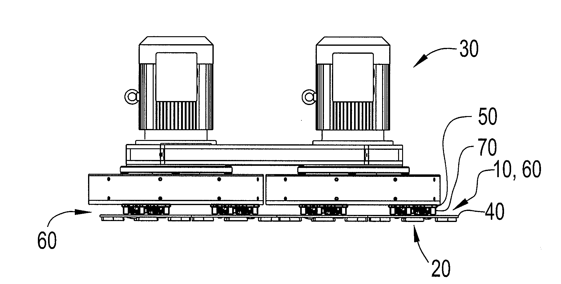
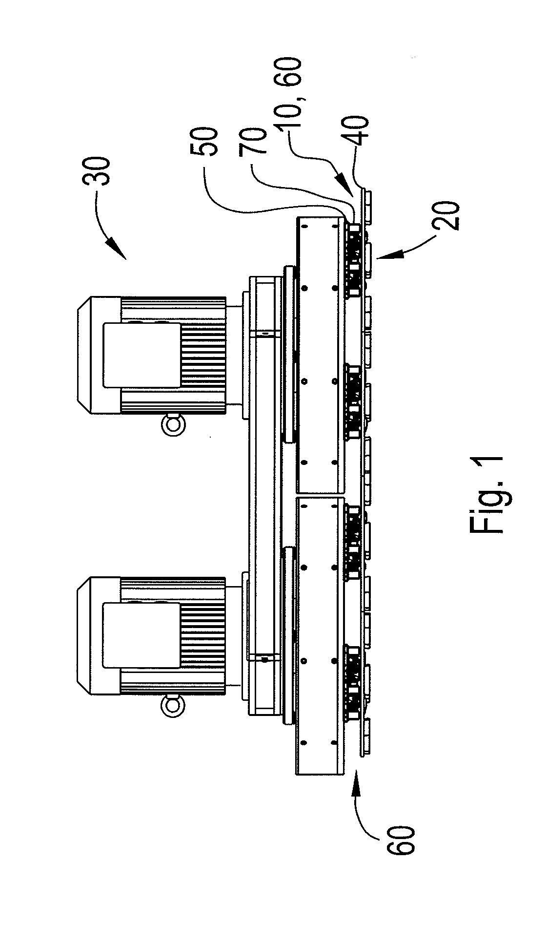
[0026]FIG. 1 indicates a machine 30 for machining surfaces on floors or roads, preferably having concrete or stone as a wearing layer, with at least one abrading, machining or grinding tool 20, each tool may be detachably mounted on a tool holder (not shown) that in turn is detachably mounted onto a grinding holder 10 according to the invention or each tool may be directly mounted onto the inventive grinding holder as shown in FIG. 1. The tool 20 may comprise at least one rotating plate adapted for machining of surfaces by means of at least one surface contacting machining disc (not shown) with machining bits, which is driven by a power source, e.g. motors as indicated in FIG. 1, as is explained in more detail in for example the patent publication WO 94 / 08752. In this document, the grinding machine comprises two motors, each motor separately rotating one or more tools via a belt transmission. The driving of the tools may also be performed by direct drive. Moreover, the invention doe...


PUM

PropertyMeasurementUnit
Shapeaaaaaaaaaa
Distanceaaaaaaaaaa
Elasticityaaaaaaaaaa

Abstract

The invention relates to a grinding holder (10) for connecting a rotary driven tool (20) to a device (30) for machining floor and road surfaces, comprising a first plate member (40) for detachable attachment of the tool (20), and a second plate member (50) for detachable attachment to the machining device (30).

Description

TECHNICAL FIELD OF THE INVENTION[0001]The present invention relates to a tool and tool holder for machining floors, more specifically a grinding holder that holds at least one such tool and tool holder during machining.DESCRIPTION OF RELATED ART[0002]Today, tools for machining stone or concrete floors or road surfaces, i.e. primarily grinding and polishing but also cutting, milling or crushing such surfaces and / or cleaning these surfaces by removing coatings on them with the object of producing plane, clean and / or smooth surfaces commonly use a machining appliance which carries one or more rotatably mounted plates that in turn carries one or more machining elements, e.g. in the form of discs that are smaller than the carrier plates and adapted to be rotated in relation to the carrier plates for machining the surface. This machining disc contacts the surface by means of different types of cutters / bits while performing a movement in a plane in parallel to the rotating carrier plates, ...

Claims


Application Information

Patent Timeline
IPC IPC(8): B24B41/047B24B23/02
CPCB24B7/186B24B41/047B24B7/22
Inventor KILGREN, KARETHYSELL, HAKANSUNESSON, JOHAN
Owner HUSQVARNA AB
Why Eureka
Try Eureka