
Electrode for stimulating cranial nerves and substrate comprising the same

a technology of cranial nerves and electrodes, applied in the direction of head electrodes, internal electrodes, therapy, etc., can solve the problems of poor mechanical stability and poor machinability of electrodes, difficult integration and miniaturization of such electrodes, and conventional electrodes for stimulating cranial nerves are not suitable for implementation, etc., to achieve simple process, easy insertion, and easy machined

Inactive Publication Date: 2010-06-10
ELECTRONICS & TELECOMM RES INST
View PDF6 Cites 21 Cited by
  • Summary
  • Abstract
  • Description
  • Claims
  • Application Information

AI Technical Summary

Benefits of technology

[0011]Accordingly, the present invention has been made keeping in mind the above problems occurring in the related art. An object of the present invention is to provide an electrode for stimulating cranial nerves, which can employ metal wires having a diversity of shapes and into which the metal wires can be easily inserted.
[0012]Further, another object of the present invention is to provide an electrode for stimulating cranial nerves, to which a machining method such as mechanical polishing, welding or the like is applicable and which can with ease be additionally machined.
[0013]Furthermore, another object of the present invention is to provide an electrode for stimulating cranial nerves, which can ensure a micro tube using a simple process and can supply drugs to the nerve system at low cost.
[0016]According to the present invention, the electrode for stimulating cranial nerves can employ a diversity of shapes of metal wire which can be easily inserted. The electrode can employ a machining method such as mechanical polishing, welding, or the like, and can be additionally machined with ease. Further, according to the present invention the electrode can ensure the micro tube using a simple process so as to supply drugs to the nerve system at a low cost.

Problems solved by technology

Further, even after application of the bio-stable polymer, the electrode has poor mechanical stability and poor machinability.
For the reason, it is difficult to integrate and miniaturize such electrodes.
Thus, the conventional electrode for stimulating cranial nerves is not suitable for the implementation of an embedded electric stimulating system, which essentially requires the integration and miniaturization of an electrode.
However, semiconductor based machining using the MEMS process has problems in that the machining cost is expensive and in that the semiconductor substrate is harmful to the human body and thus it should be separately sealed with a bio-stable polymer or the like.

Method used


Image

  • Electrode for stimulating cranial nerves and substrate comprising the same
  • Electrode for stimulating cranial nerves and substrate comprising the same
  • Electrode for stimulating cranial nerves and substrate comprising the same

Examples


Embodiment Construction

[0021]Reference will now be made in greater detail to a preferred embodiment of the invention, an example of which is illustrated in the accompanying drawings.

[0022]I. Electrode for Stimulating Cranial Nerves

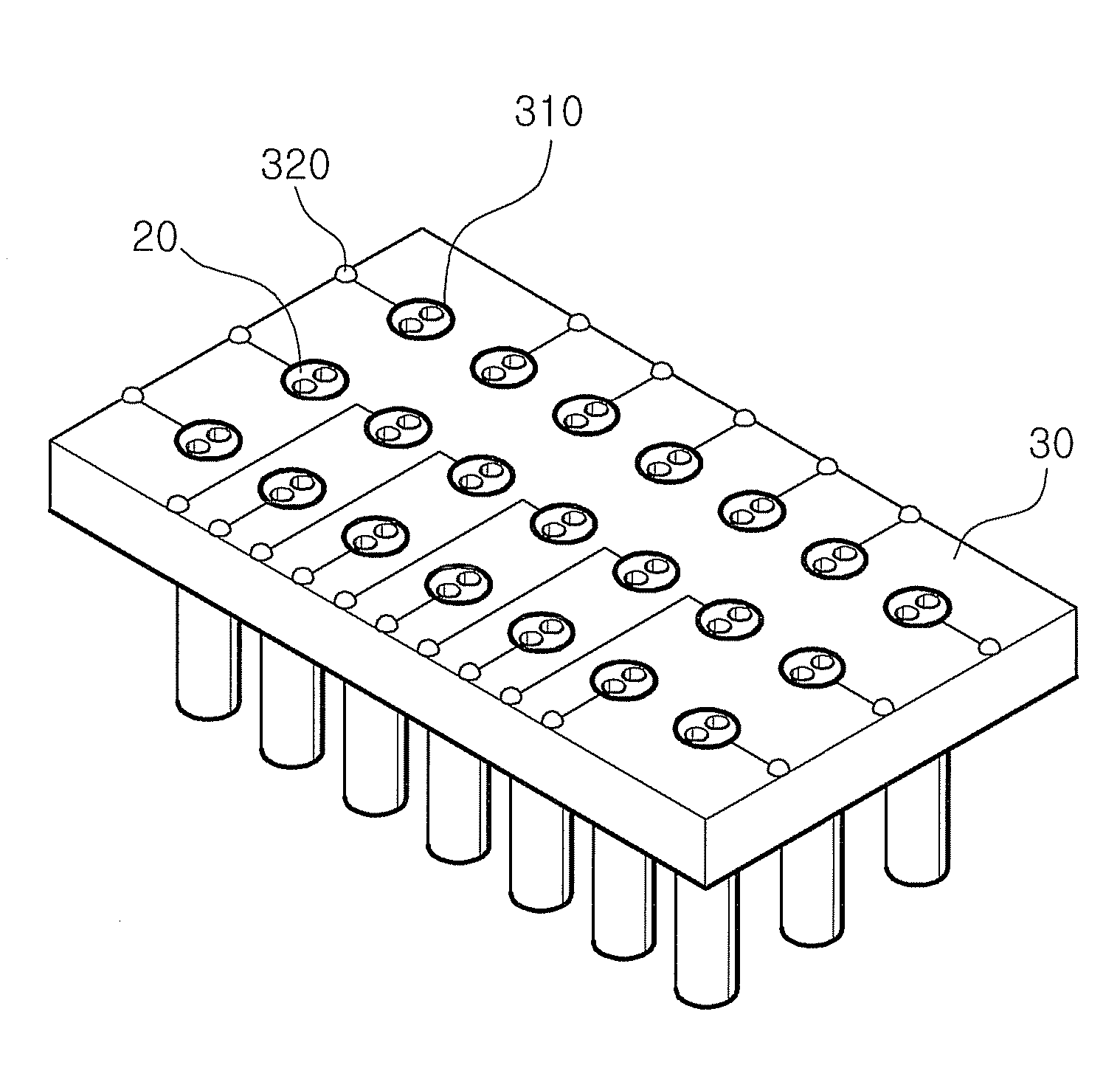
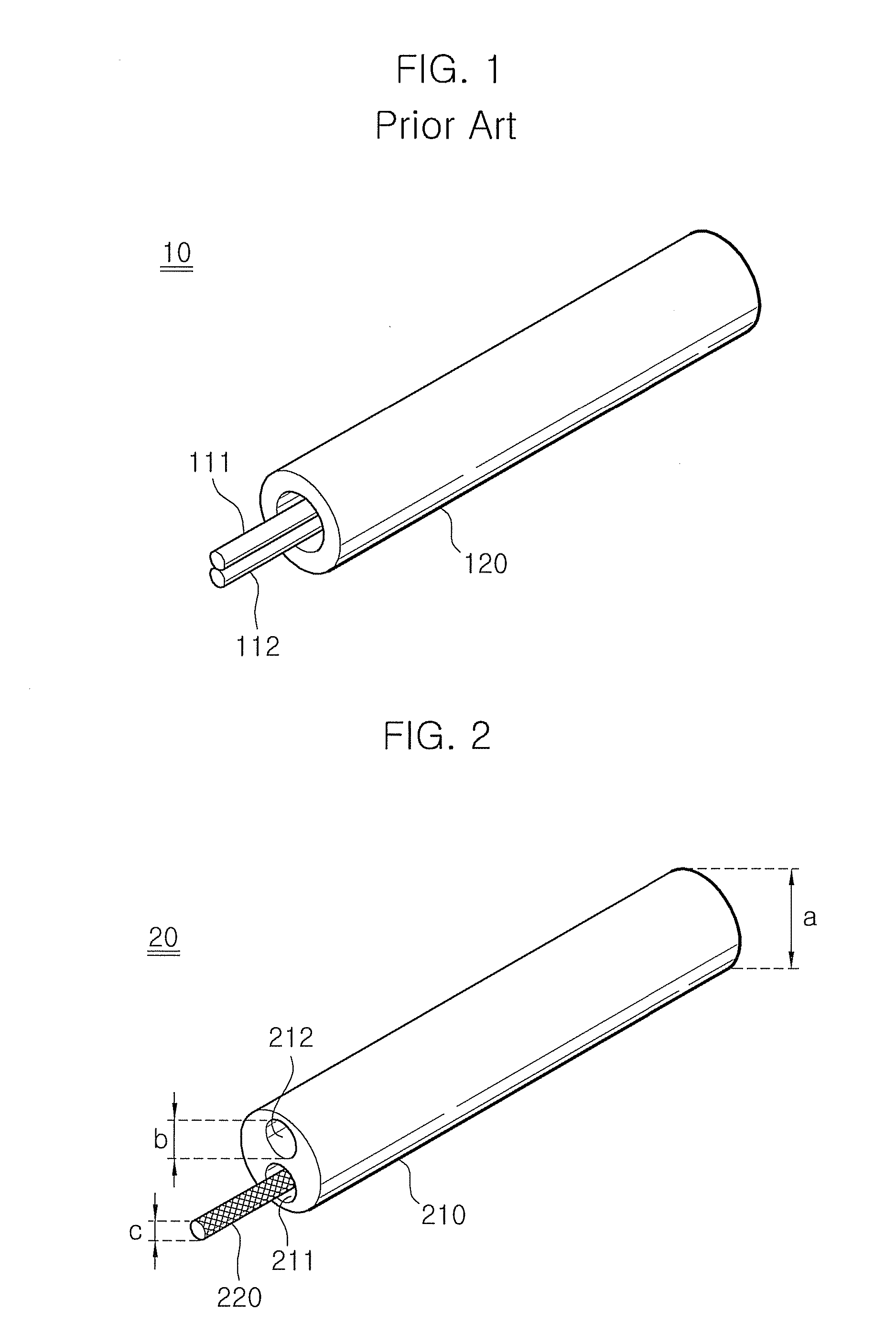
[0023]FIG. 2 is a perspective view illustrating an electrode for stimulating cranial nerves according to an embodiment of the present invention.

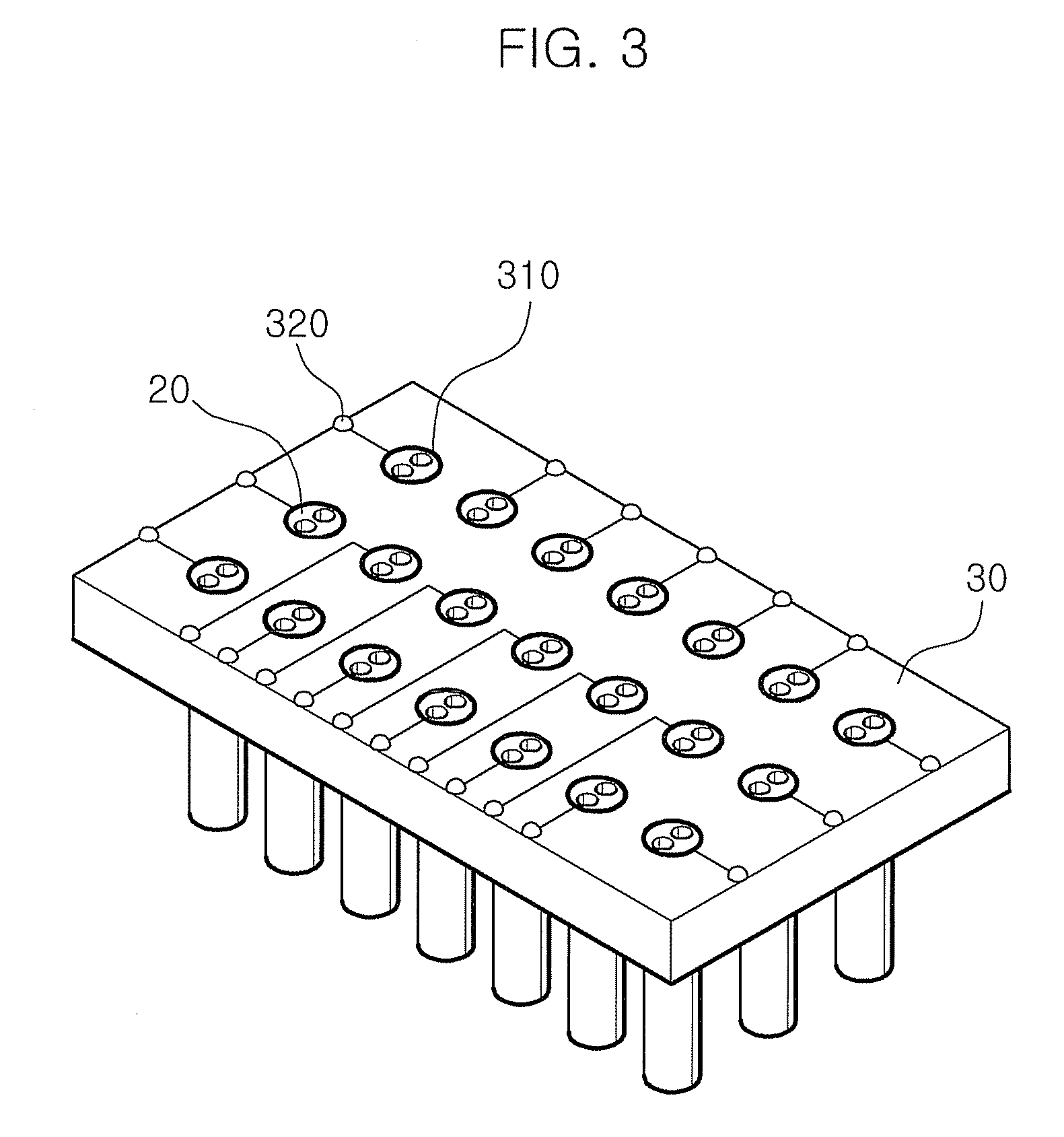
[0024]Referring to FIG. 2, the electrode 20 for stimulating cranial nerves comprises a glass fiber 210 and a metal wire 220.

[0025]The electrode 20 for stimulating cranial nerves has a diameter in the range of preferably 100 μm to 290 μm, more preferably 150 μm to 250 μm. If the diameter satisfies the above-mentioned range, it is advantageous in that an electrode implements the integration and miniaturization, which are essential elements for an embedded electrode for stimulating cranial nerves.

[0026]The glass fiber 210 has first and second holes 211 and 212, and the metal wire 220 is disposed in the first hole 211. The second hole 212 is...


PUM


Abstract

An electrode for stimulating cranial nerves comprising a glass fiber having first and second holes, and a metal wire disposed in the first hole.

Description

RELATED APPLICATIONS[0001]The present application claims priority to Korean Patent Application Serial Number 10-2008-0125473, filed on Dec. 10, 2008, the entirety of which is hereby incorporated by reference.BACKGROUND OF THE INVENTION[0002]1. Field of the Invention[0003]The present invention relates to an electrode for stimulating cranial nerves and a substrate comprising the same. More specifically, the present invention relates to an electrode for stimulating cranial nerves comprising a glass fiber and a metal wire, and a substrate comprising the electrode.[0004]2. Description of the Related Art[0005]Generally, stimulating cranial nerves or nerve cells with electricity is very useful for treating strokes, preventing attacks, alleviating pain, performing remote control of animal, etc. Electrodes providing the electric stimulus are classified into mono-polar and bi-polar electrodes. The bi-polar electrode has the characteristic of being capable of minimizing a stimulus applied to u...

Claims


Application Information

Patent Timeline
IPC IPC(8): A61N1/05A61N1/04
CPCA61N1/0551A61N1/0529A61B18/14A61N1/04
Inventor JUNG, SANGDONCHUNG, MYUNGAEKIM, SANGHYEOBKIM, GOOKHWAKIM, IKHYUN
Owner ELECTRONICS & TELECOMM RES INST
Learn More