Automotive exhaust system

a technology for exhaust systems and automobiles, applied in the direction of exhaust treatment, machines/engines, gas passages, etc., can solve the problems of preventing efficient escape of exhaust gases from within the cylinder, affecting vehicle performance, fuel consumption, efficiency and power, and affecting vehicle performance, etc., to achieve quick and efficient expulsion of exhaust gases

Inactive Publication Date: 2010-06-17
GRUDYNSKI III JOHN M
View PDF10 Cites 14 Cited by
  • Summary
  • Abstract
  • Description
  • Claims
  • Application Information

AI Technical Summary

Benefits of technology

[0008]The improved automotive exhaust system of the present invention includes a plurality of exhaust pipes at the proximal end that join into a common collector at the distal end. The collector includes a venturi at the point of entry of the exhaust gases from the multiple exhaust pipes. The venturi has a cross-sectional area smaller than that of the cross-sectional area of the pipes or the cross-sectional area of the main body of the connector. In turn, exhaust

Problems solved by technology

This directly affects vehicle performance, fuel consumption, efficiency and power.
Any exhaust gases remaining in the exhaust system may have a tendency to stagnate or even reverse direction due to a change in vacuum.
Ultimately, this force may exert back pressure on the piston, thereby preventing efficient escape of the exhaust gases from within the cylinder.
Additional power is wasted if the piston has to push against t

Method used


Image

  • Automotive exhaust system
  • Automotive exhaust system
  • Automotive exhaust system

Examples


Embodiment Construction

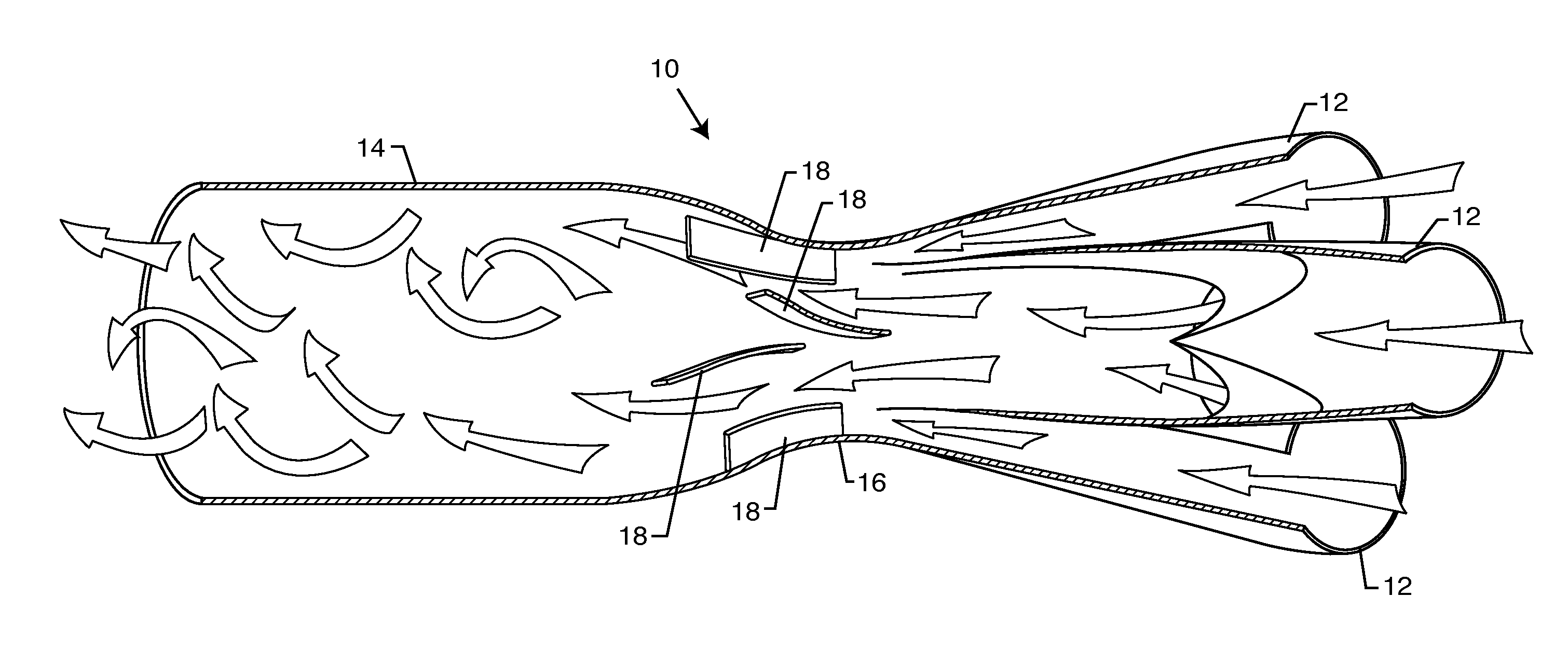
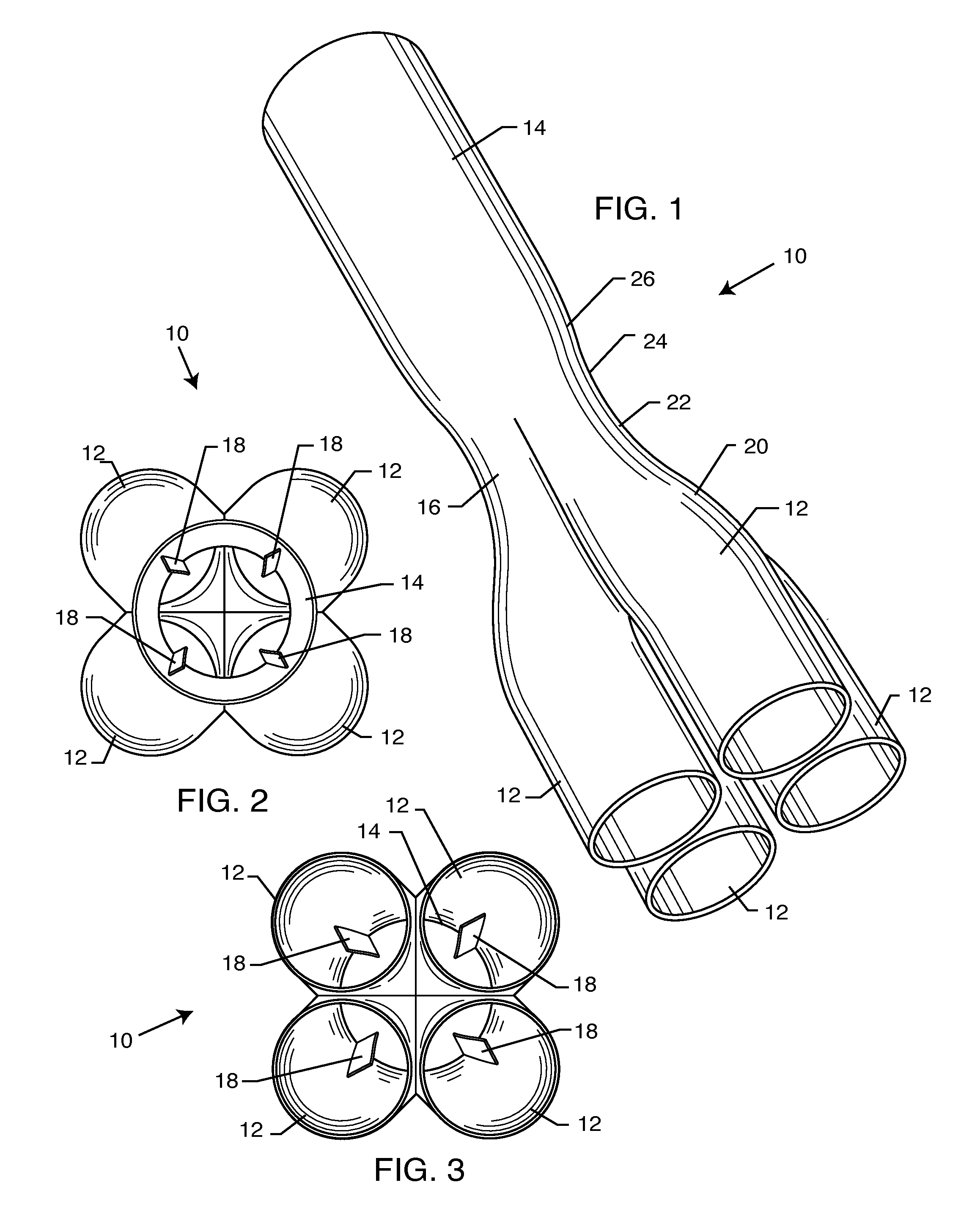
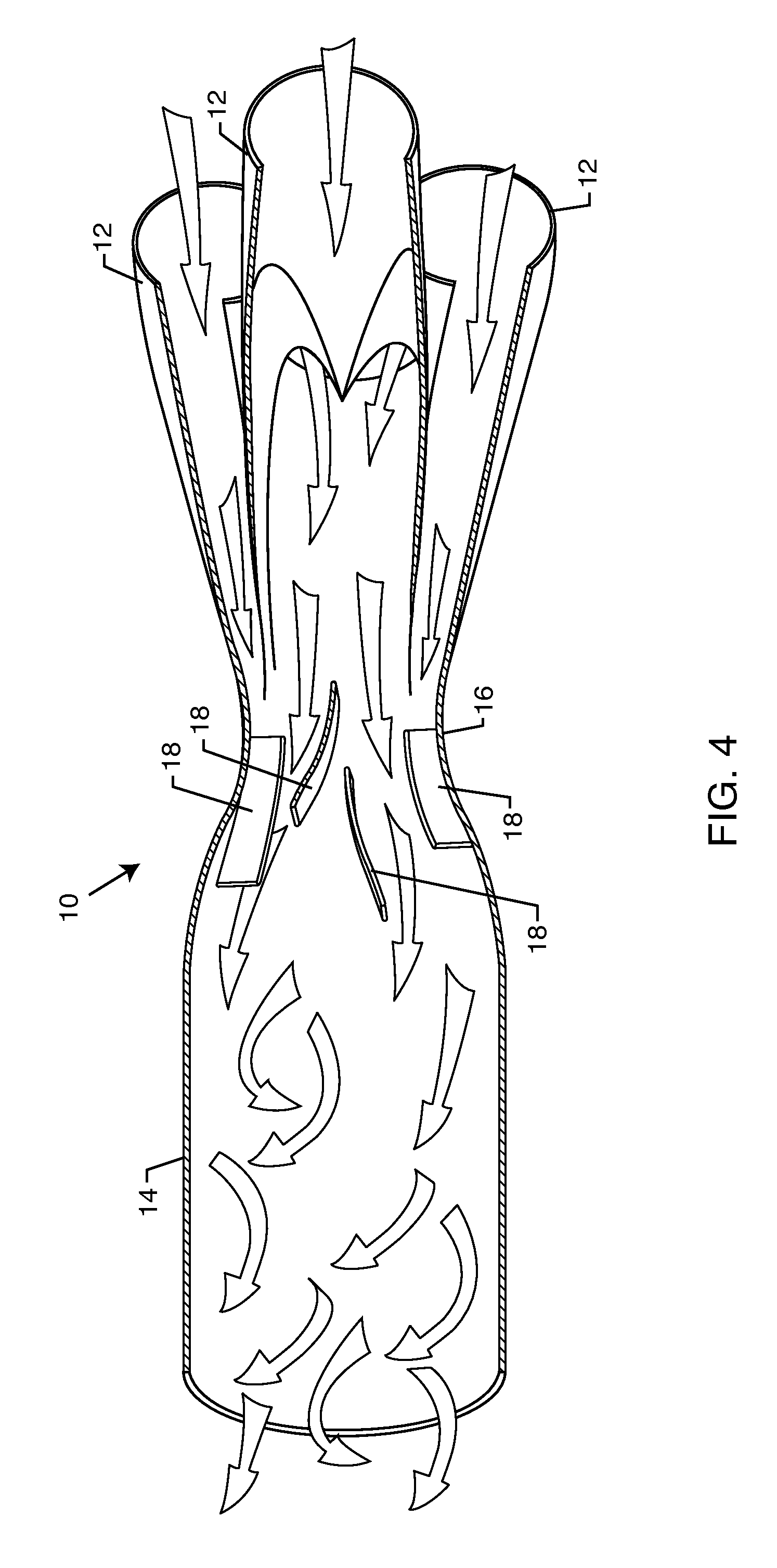
[0015]As shown in the drawings for purposes of illustration, the present invention for an improved automotive exhaust system is referred to generally by the reference number 10. The improved automotive exhaust system 10 generally includes a plurality of exhaust pipes 12 that feed into a collector 14 through a venturi 16. FIG. 1 illustrates four exhaust pipes 12 converging into a single collector 14. Other embodiments may include any one of a number of plurality of exhaust pipes 12 that feed into a single collector 14, such as two, three, five, etc., in accordance with the present invention. In this respect, the exhaust pipes 12 are shown in FIG. 1 sectioned off from an exhaust header for purposes of describing the improved automotive exhaust system 10 of the present invention. A person of ordinary skill in the art will readily recognize that the exhaust pipes 12 extend back into the exhaust header that couples to the IC engine piston cylinders. That is, during the exhaust stroke in ...


PUM


Abstract

The automotive exhaust system includes a plurality of exhaust pipes that feed into a common collector. The collector includes a venturi at the point where the exhaust gases enter the collector from the multiple exhaust pipes. The exhaust gases accelerate through the venturi by virtue that the venturi has a cross-sectional area smaller than that of the exhaust pipes and the collector. A plurality of vanes located in the venturi further accelerate the exhaust gases into a spinning vortex along the interior surface of the main body of the collector to efficiently and quickly expel the exhaust gases out from within the automotive exhaust system. The diameter of the venturi relative to the collector is specific to each diameter of tubing as matched with the corresponding vehicle specifications.

Description

BACKGROUND OF THE INVENTION[0001]The present invention relates to an automotive exhaust system. More particularly, the invention relates to an automotive exhaust system having an improved collector that accelerates the expulsion exhaust gases out the tailpipe.[0002]Over the years, various exhaust systems have been designed to improve the efficiency and power output of four-stroke internal combustion (“IC”) engines. Improvements in engine components and “super tuning,” as is more typically done in racing systems, have produced significant increases in engine power, especially with respect to the exhaust system. The efficiency of expelling exhaust gases resultant from the combustion process in an IC engine is important to the overall efficiency of the engine. For example, increasing exhaust system efficiency can reduce fuel consumption of the IC engine while maintaining and improving output power.[0003]The exhaust gases in an IC engine exit the piston cylinder chamber through an exhau...

Claims


Application Information

Patent Timeline
IPC IPC(8): F01N13/08
CPCF01N13/08F01N2470/30F01N2240/20
Inventor GRUDYNSKI, III, JOHN M.
Owner GRUDYNSKI III JOHN M
Why Eureka
Try Eureka