Advanced wave energy converter control

a technology of energy converters and wave energy, applied in the direction of electric generator control, mechanical equipment, machines/engines, etc., can solve the problems of less than optimal, and achieve the effects of improving control systems, less errors, and greater power efficiency

Active Publication Date: 2010-06-17
OCEAN POWER TECHNOLOGIES
View PDF7 Cites 48 Cited by
  • Summary
  • Abstract
  • Description
  • Claims
  • Application Information

AI Technical Summary

Benefits of technology

[0011]Applicant's invention includes a method and apparatus for using a combination of “predictive” and “actual” signals to control the WEC. The combination of signals includes reliance, in part, on the predicted information obtained from a wave sensor and, in part, on the actual response (e.g. relative velocity) of the components of the WEC. An appropriate selection and combination of these signals results in an improved control system with less error and a WEC system yielding greater power efficiency.
[0012]A WEC system embodying the invention includes a sensor, generally external to the WEC, for sensing the amplitude (and / or other selected characteristics, such as frequency) of an incoming wave and a wave sensing and responsive subsystem for supplying corresponding “predictive” signals to a control computer which includes data processing capability. Signals representative of the selected actual conditions (e.g. the velocity) of the WEC are also supplied to the control computer which is programmed to process the predicted and actual information in order to generate appropriate signals (forces) to the components of the WEC such that the average wave power captured by the PTO, and made available to a load, is maximized.

Problems solved by technology

Thus, relying solely on the predicted information to position and move the WEC components does not compensate for “wave errors” and leads to less than optimal results since the WEC components may not be positioned at their optimum point(s) and do not undergo optimum motions.

Method used


Image

  • Advanced wave energy converter control
  • Advanced wave energy converter control
  • Advanced wave energy converter control

Examples


Embodiment Construction

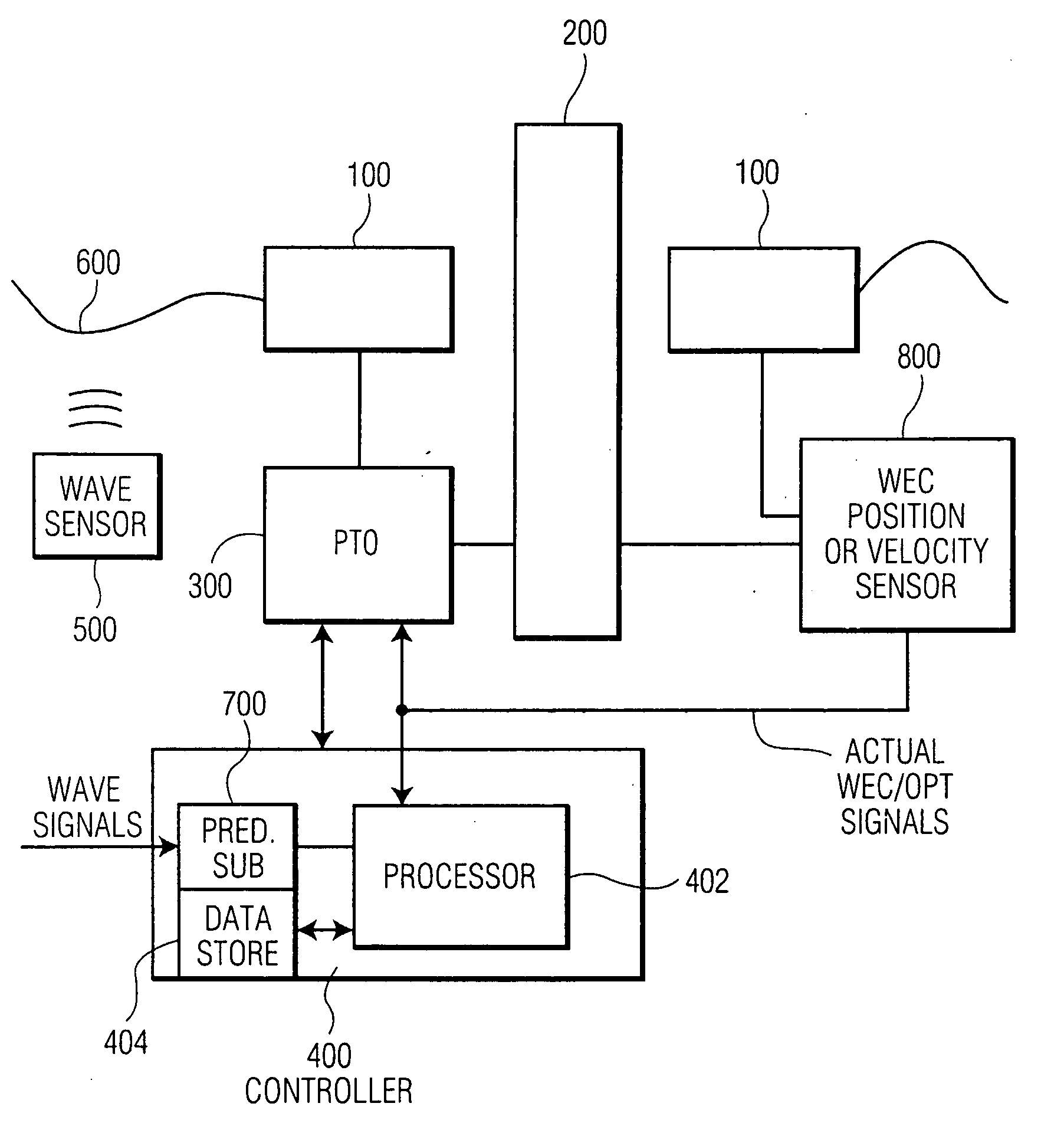
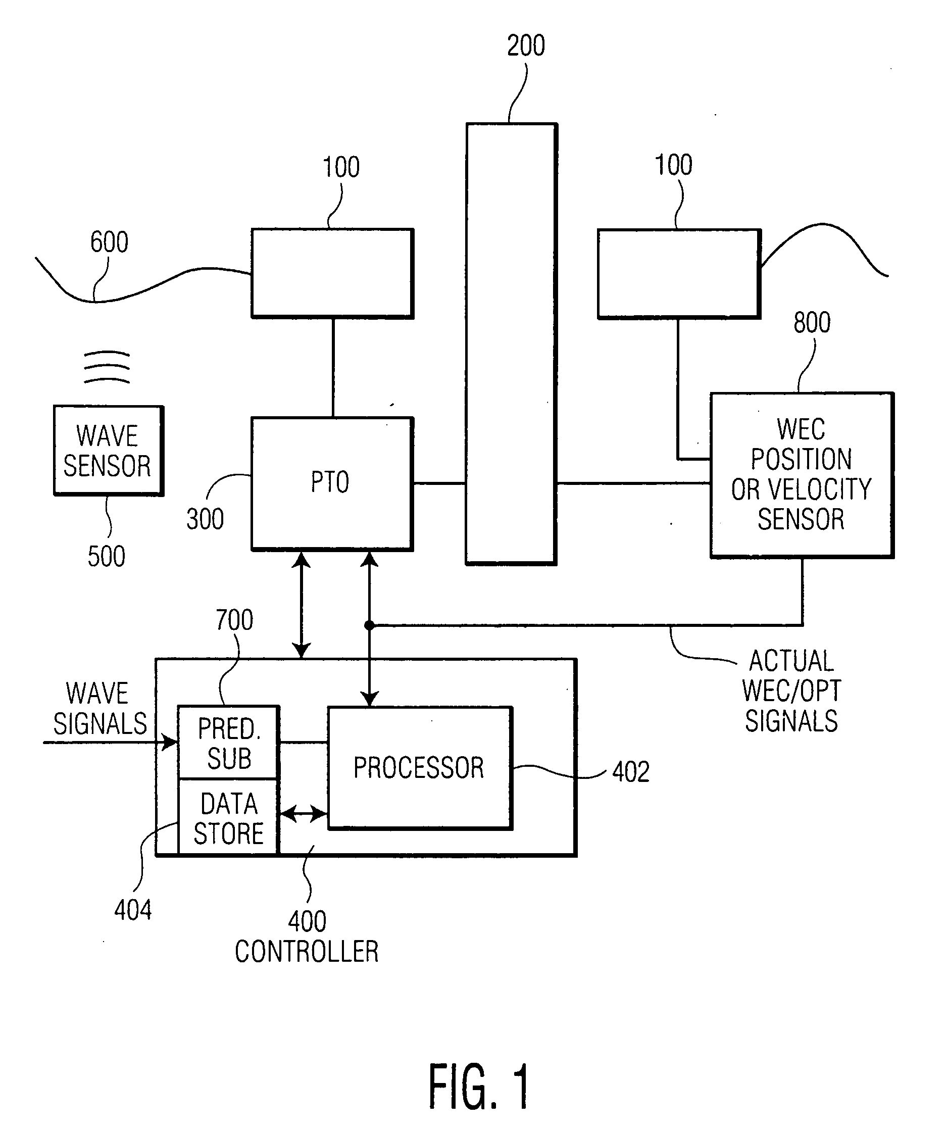
[0041]FIG. 1 shows the main components of a wave energy converter (WEC) system for use in practicing the invention. The WEC includes a first body or float, 100, and a second body or spar, 200. The first body (e.g., float) is designed to move generally in phase with the waves and the second body (e.g., spar) is designed to move generally out of phase with the waves, or to be held relatively fixed at mechanical ground. A power take-off (PTO) device, 300, is coupled between the first and second bodies and converts their relative motion into useful energy and is capable of receiving power from, or transmitting power to, the first and second bodies. The PTO may be any suitable device which can perform this function. The two bodies, along with the PTO, comprise a wave energy converter, or WEC.

[0042]Signals from an upstream wave detection system 500, responsive to incoming waves 600, are supplied to a wave predictive subsystem 700 whose signals are supplied to a data processor 402 function...


PUM


Abstract

A wave energy converter (WEC) system includes first and second bodies which can move relative to each other in response to waves and a power-take-off (PTO) device coupled between the two bodies to convert their relative motion into energy. A sensor is used to sense selected characteristics of an incoming wave and produce signals which are applied to a control computer for predicting the impact of the incoming waves on the WEC. Simultaneously, signals indicative of the actual conditions (e.g. the velocity) of the WEC are also supplied to the control computer which is programmed to process the predicted and actual information in order to generate appropriate signals (forces) to the components of the WEC such that the average wave power captured by the PTO is maximized.

Description

[0001]This invention claims priority from provisional application Ser. No. 61 / 130,529 filed May 30, 2008 for Advanced Wave Energy Converter Control whose contents are incorporated herein by reference.BACKGROUND OF THE INVENTION[0002]This invention relates to apparatus and methods for controlling the response of a wave energy converter (WEC) so as to increase the efficiency of the WEC in producing energy. The invention also relates to control systems for wave energy conversion devices, and more particularly to a control algorithm for capturing wave energy more efficiently.[0003]Wave energy converters (WECs) of interest generally include first and second bodies which can move relative to each other when placed in a body of water and subjected to the forces of the waves. Typically, one body, referred to as a float or shell, is designed to move in phase with the waves and the other body, referred to as a column or spar, is designed to either move out of phase with the waves (resulting i...

Claims


Application Information

Patent Timeline
Patent Type & Authority Applications(United States)
IPC IPC(8): F03B13/20H02P9/04
CPCY02E10/38F03B13/16F05B2270/20F05B2260/821F03B15/00Y02E10/30
Inventor GERBER, JAMES S.
Owner OCEAN POWER TECHNOLOGIES
Why Eureka
Try Eureka