
Methods and instruments for estimating target motion

Active Publication Date: 2010-06-17
TRIMBLE INC
View PDF12 Cites 77 Cited by
  • Summary
  • Abstract
  • Description
  • Claims
  • Application Information

AI Technical Summary

Benefits of technology

[0013]A further object of the present invention is to provide an improved measuring instrument and a method for such an instrument for regaining lock to a target after the target has been lost during a measurement session in fast and efficient manner.
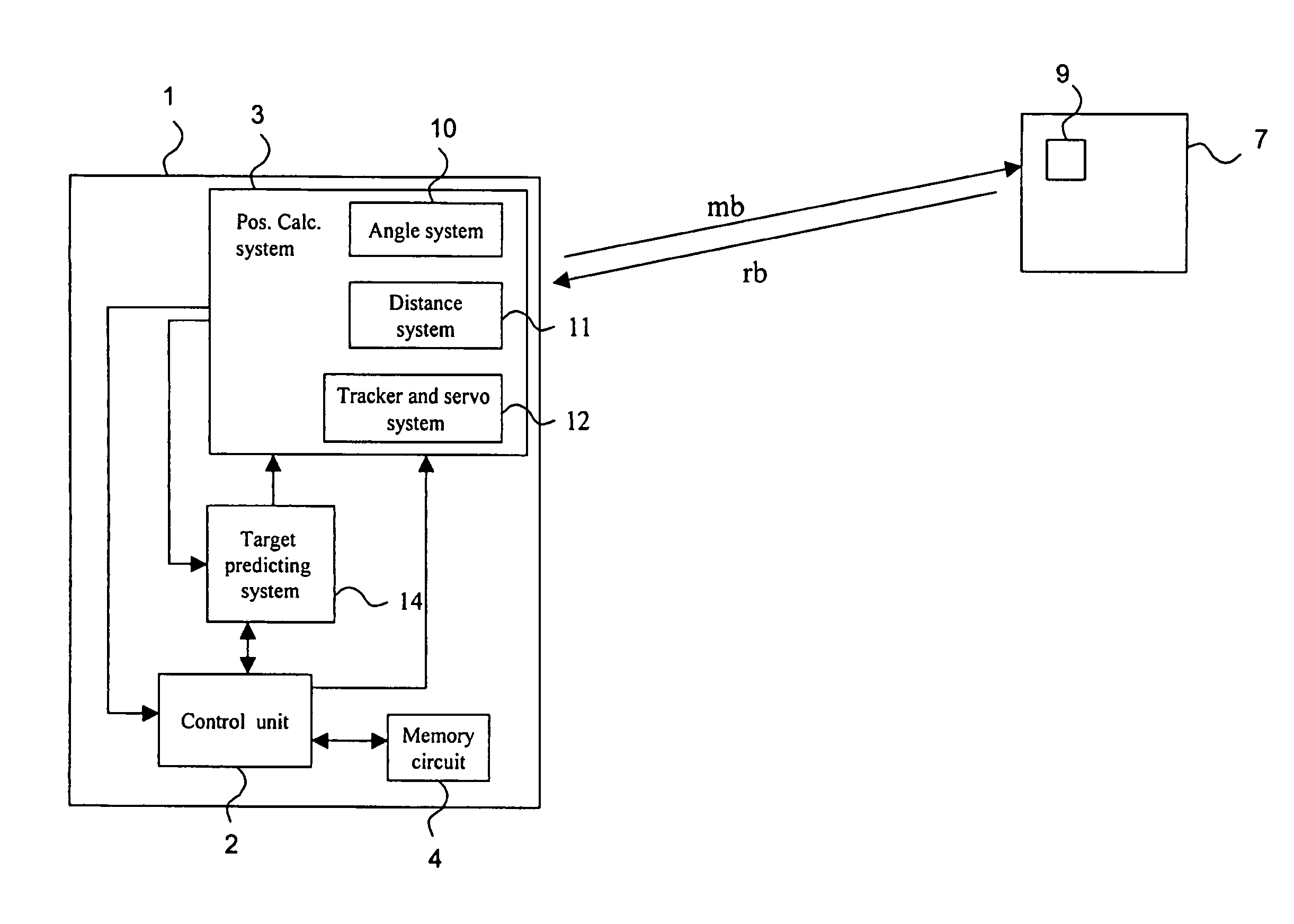
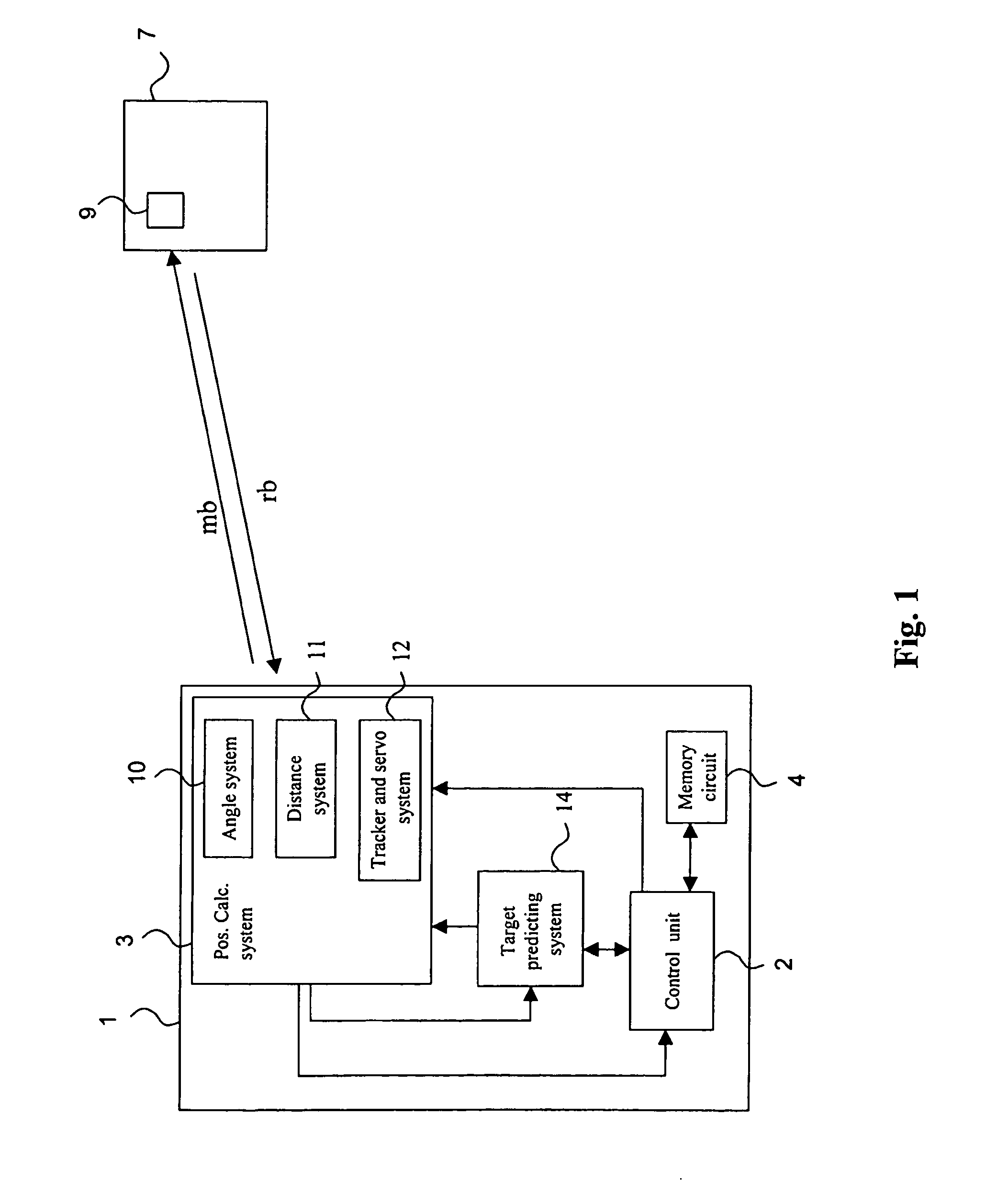
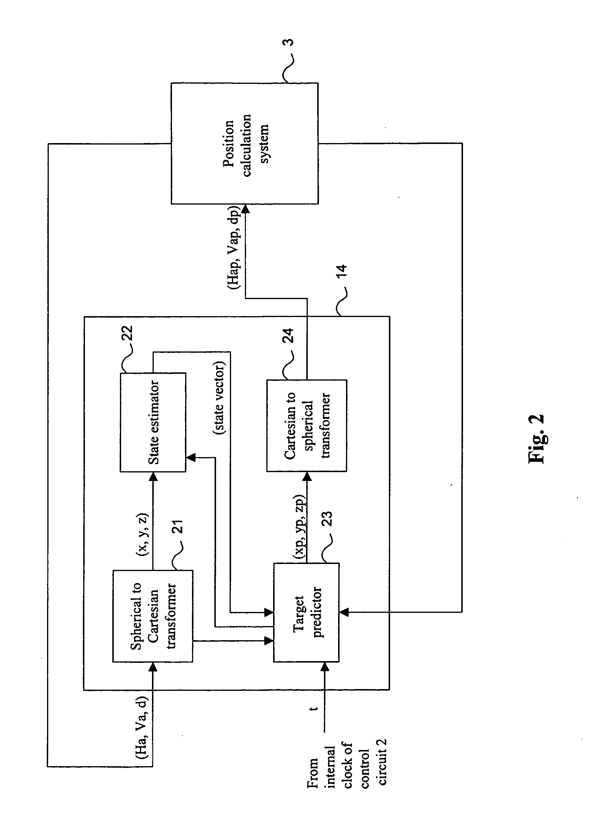
[0019]Hence, the present invention is based on the idea of creating a model of the motion of a target or object based on measured angles and measured distance to the target. When a target is lost due to, for example, that the measuring beam is obstructed, the distance measuring system and the tracker and servo system may use this model to estimate where the target will be at a future time point, i.e. estimate the distance and angles to the target. Thereby, the distance measuring system and the tracker and servo system will have a good approximation of the position of the target and may thus start searching for the target with this approximate position as a first guess.
[0022]Furthermore, the distance measuring system utilizes a narrow sampling window, i.e. a short period of time, which entails that it is able to sample only a short period of time for each returning pulse. Consequently, in order to obtain measurement data from a certain returning pulse, the distance measuring system must know approximately when it will be returning according to the prior art methods. Since the time of flight corresponds to the distance to the target this means that the distance measuring system has to know the approximate distance to the target. When measuring against an unknown target, the distance measuring system will move the sampling window and search for the returning pulse, which make take time. Once the target has been found, the distance measuring system will keep the sampling window locked and will start shifting or moving the sampling window if the target starts moving to compensate for the distance change. If the measuring been is obstructed for some reason, for example, due to that the target is hidden temporarily behind an obstacle, the distance measuring system may loose the target, i.e. the sampling window may not capture the returning pulse. In order to resume the distance measuring procedure, the distance measuring system have to estimate the distance to the target when it reappears after the obstacle, which may be difficult due to, for example, a non-linear moving velocity of the target. According to the present invention, the distance measuring system uses the predicted position determined by the calculated model of the path of the target to estimate the distance to the target. Accordingly, the distance measuring system will have a good estimate where to search for the returning pulse and how to move the sampling window and may thus find the target in a significantly short period of time in comparison with the prior art methods.
[0029]According to yet another embodiment of the present invention, the prediction model is used in case where the measuring system performs measurement against more than one target. For example, in a case where the measuring system measures against two moving targets. The prediction model can in such a case be utilized in that when the instrument shifts from a first target, which have been tracker for a while and for which a prediction model has been calculated, to a second target, the prediction model for the first target is saved and may thus be used to predict the movement of the first target during measurements against the second target. Thereby, it is possible to fast regain lock to the first target again after a shift from the second target back to the first object since the prediction model was saved and used to predict the position for the first target.

Problems solved by technology

This narrow angle of view entails problem, for example, when the target is temporarily lost, i.e. the reflecting signal is lost, when the target for instance is hidden behind an obstacle when the object moves behind the obstacle.
A similar problem arises in the distance meter, which uses a pulse measurement technique where the exact time a transmitted pulse returns from the target is determined.
If the measuring signal has been obstructed for some reason, for example, due to that the target is hidden temporarily behind an obstacle, the distance meter may loose the target, i.e. the sampling window may not capture the returning.
In order to resume the distance measuring procedure, the distance meter have to estimate the distance to the target when it reappears after the obstacle, which may be difficult due to, for example, a non-linear moving velocity of the object.
Accordingly, the distance meter may have to search for the returning pulse and move the sampling window, which may take time.

Method used


Image

  • Methods and instruments for estimating target motion
  • Methods and instruments for estimating target motion
  • Methods and instruments for estimating target motion

Examples


Embodiment Construction

[0041]With reference first to FIG. 1, an embodiment of a measuring instrument, such as a total station or a geodetic instrument, according to the present invention will be discussed.

[0042]The total station is a distance measuring instrument with an integrated distance and angular measurement, i.e. with combined electronic, optical and computer techniques. Such a total station gives both the distance as well as the vertical and horizontal direction towards an object or a target, whereby the distance is measured against a reflecting surface or a reflector, e.g. of the corner cube type. A total station is furthermore provided with a computer or control unit with writable information for measurements to be performed and for storing data obtained during the measurements. Preferably, the total station calculates the position of a target in a fixed ground-based coordinate system. In, for example, WO 2004 / 057269 by the same applicant, such a total station is described in more detail.

[0043]E...


PUM


Abstract

The present invention relates to a measuring instrument and methods for such a measuring instrument for tracking a moving object, measuring a distance to an object. According to the invention, sets of target position data including at least horizontal (Ha) and vertical angle (Va) between the measuring instrument (1) and said at least one target (9) in consecutive measurements during a measurement session are obtained (40; 50; 60; 70); a model describing a path of and / or a distance to the target (9) is calculated; at least a present position of the target is estimated (44; 53; 65; 74) using the model; and, the estimated position of the target (9) is used (45; 56; 67; 79) when searching for the target (9).

Description

FIELD OF THE INVENTION[0001]The present invention generally relates to methods for determining the position of moving objects such as a vehicle using a position-determining apparatus such as a surveying unit. The present invention particularly concerns a measuring instrument and methods for such a measuring instrument for tracking a moving object, measuring a distance to an object.BACKGROUND[0002]The art of surveying involves the determination of unknown positions, surfaces or volumes of objects or setting out of known coordinates using angle and distance measurements taken from one or more positions. In order to make these measurements, a surveying device frequently used is a distance measuring instrument with an integrated distance and angular measurement of the type which is called a total station, i.e. with combined electronic, optical and computer techniques. A total station is furthermore provided with a computer or control unit with writable information for measurements to be...

Claims


Application Information

Patent Timeline
IPC IPC(8): G01S17/66
CPCG01C15/002G01S17/66G01S13/72
Inventor NORDENFELT, MIKAELKLANG, THOMAS
Owner TRIMBLE INC
Learn More