Capacitor
a technology of capacitors and capacitors, applied in the field of capacitors, can solve the problems of complex connection jobs, capacitor units cannot be used by coupling a plurality of capacitors, and the size cannot be reduced
- Summary
- Abstract
- Description
- Claims
- Application Information
AI Technical Summary
Benefits of technology
Problems solved by technology
Method used
Image
Examples
embodiment 1
Preferred Embodiment 1
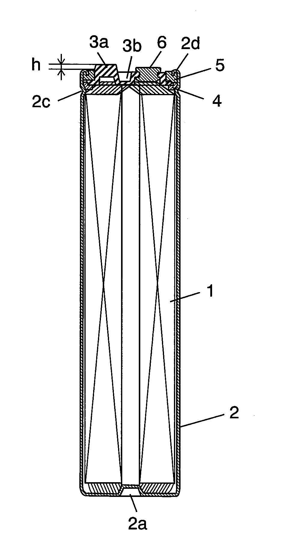
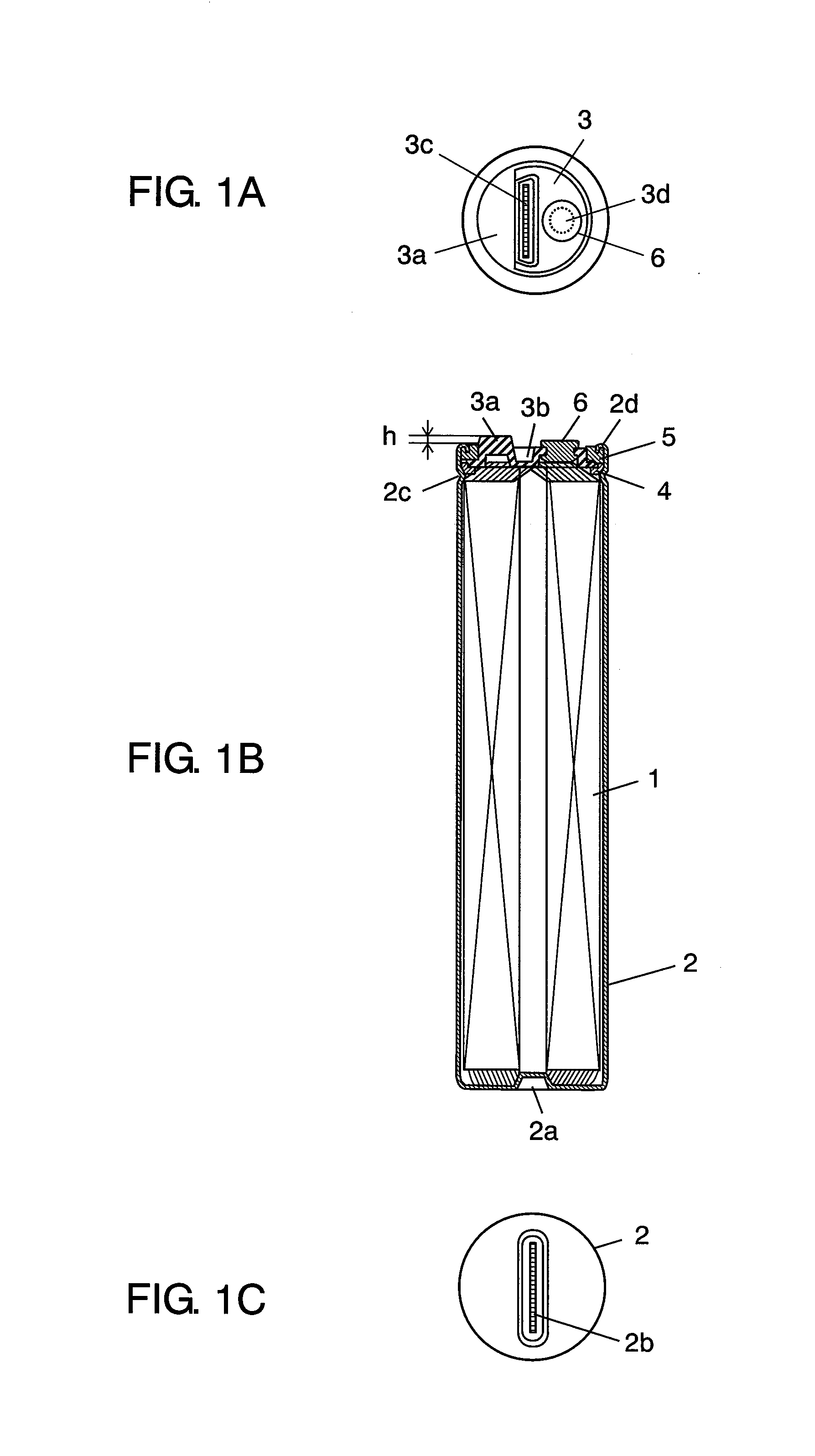
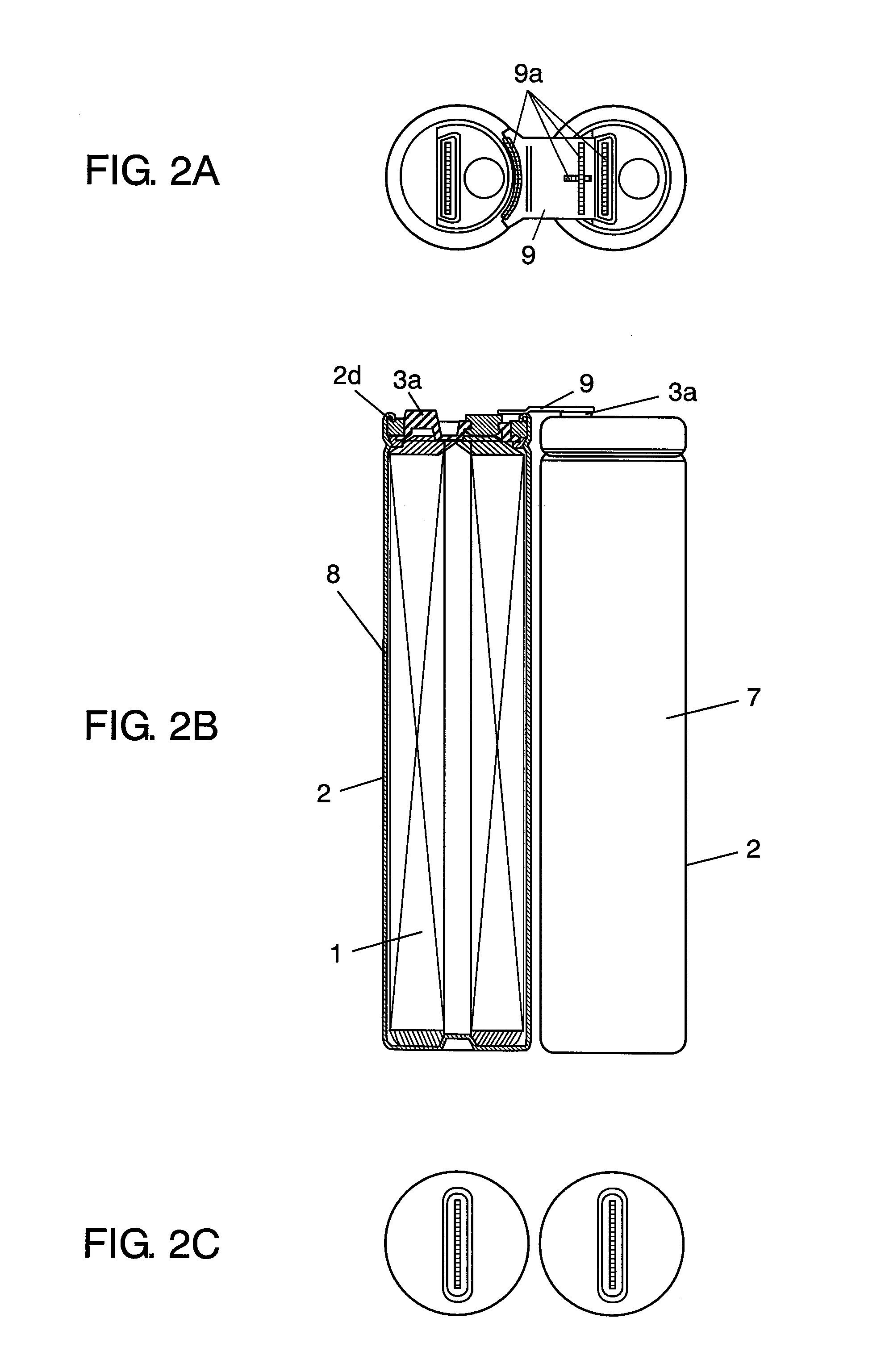
[0070]FIGS. 1A, 1B, 1C show a plan view, a front sectional view, and a bottom view of the capacitor according to preferred embodiment 1 of the present invention, respectively. As shown in FIGS. 1A, 1B, 1C, the capacitor has capacitor element 1. Capacitor element 1 is formed by winding a pair of positive and negative electrodes forming polarizable electrode layers formed on a current collector made of an aluminum foil as a metal foil by deviating positions mutually in reverse directions, with a separator interposed between them (none shown), and an anode and a cathode are taken out from both sides of capacitor element 1 (upper and lower sides in FIG. 1B). That is, capacitor element 1 is configured so that ends of positive and negative elements may be exposed mutually in reverse directions.
[0071]The capacitor includes metal case 2 of cylindrical shape with a bottom formed of aluminum including capacitor element 1 together with an electrolyteelectrolyte (not shown...
embodiment 2
Preferred Embodiment 2
[0080]Preferred embodiment 2 is similar to preferred embodiment 1, except that the junction part provided in the terminal plate of the capacitor explained in preferred embodiment 1 is provided at two positions on the peripheral edge of the terminal plate, and corresponding parts are identified with same reference numerals, and detailed description is omitted, and only different parts are explained below along with the accompanying drawings.
[0081]FIGS. 4A, 4B, 4C show a plan view, a front sectional view, and a bottom view of the capacitor according to preferred embodiment 2 of the present invention, respectively. FIGS. 5A, 5B, 5C show a plan view, a front sectional view, and a bottom view of two capacitors coupled together, respectively, and the capacitors in preferred embodiment 2 are of type of large size and large capacity (large current).
[0082]As shown in FIGS. 4A, 4B, 4C, the capacitor includes metal case 10, and recess 10a provided in the bottom of metal c...
embodiment 3
Preferred Embodiment 3
[0086]Preferred embodiment 3 is similar to preferred embodiment 1, except that the junction part provided in the terminal plate of the capacitor explained in preferred embodiment 1 is provided in the center of the terminal plate, and corresponding parts are identified with same reference numerals, and detailed description is omitted, and only different parts are explained below along with the accompanying drawings.
[0087]FIGS. 6A, 6B, 6C show a plan view, a front sectional view, and a bottom view of the capacitor according to preferred embodiment 3 of the present invention, respectively. As shown in FIG. 6B, the capacitor of preferred embodiment 3 includes metal case 15, and recess 15a provided in the bottom of metal case 15. An electrode exposed to one end of capacitor element 1 is pressed to the inner side of recess 15a, and laser light is emitted from the outer bottom side of metal case 15 for laser welding, and by joining by laser welding or other means, the...
PUM
 Abstract
Description
Claims
Application Information
 - R&D
- Intellectual Property
- Life Sciences
- Materials
- Tech Scout
- Unparalleled Data Quality
- Higher Quality Content
- 60% Fewer Hallucinations
Browse by: Latest US Patents, China's latest patents, Technical Efficacy Thesaurus, Application Domain, Technology Topic, Popular Technical Reports.
© 2025 PatSnap. All rights reserved.Legal|Privacy policy|Modern Slavery Act Transparency Statement|Sitemap|About US| Contact US: help@patsnap.com


