Method for transmitting a multi-channel data stream on a multi-transport tunnel, corresponding computer-readable storage means and tunnel end-points

Inactive Publication Date: 2010-06-17
CANON KK
View PDF14 Cites 66 Cited by
  • Summary
  • Abstract
  • Description
  • Claims
  • Application Information

AI Technical Summary

Benefits of technology

[0053]Again, through this delay applied to each channel transported by means of the first carrier, this method makes it possible, upon reception by a receiver module (of the second tunnel end-point) of the channels transmitted on the first and second carriers, to overcome the need for a systematic temporary storage of the channels received on the first carrier. The latency is thereby diminished.
[0060]Thus, in a simple and systematic way, a minimum delay is ensured between the channels transmitted on the first and second carriers, thus making it possible to always comply with the assumption according to which the time for transmitting data sent on a first carrier supporting a transport protocol with acknowledgement is lengthier then the time for transmitting data sent on a second carrier supporting a transport protocol without acknowledgement
[0064]Thus, the invention favors the sending of important data to the detriment of less important data in order to limit the impact of congestion on the subsequent rendering of the data stream.
[0066]Thus, through the use of already existing time stamping data, it is not necessary to introduce new data. The bandwidth and the processing time when sending data is thereby improved.
[0076]Thus, the invention relies on a wholly novel and inventive approach consisting of the clocking, by the first carrier, of the sending of “important” data to the second tunnel end-point. This clocking associated with the synchronization information overcomes the need for a systematic temporary storage at reception of the channels transmitted on the first carrier. The latency is thereby diminished. The present invention therefore makes it possible to overcome the need for an additional temporary storage space on the second tunnel end-point.
[0083]Thus, the first tunnel end-point, depending on this second piece of information on synchronization, is allowed to eliminate certain channels that have to be transmitted on the second carrier in order to limit the bit rate on the tunnel and accelerate the re-absorption of congestion (on which the loss rate depends).

Problems solved by technology

However, this technique has several drawbacks.
A first drawback lies in the fact that the mechanism described in this document uses two buffer memories of variable size, necessitating temporary storage space to manage these buffers.
A second drawback lies in the fact that the solution described in these documents calls for the implementation of systematic temporary storage of all the frames received.
This induces the addition of supplementary latency in addition to that inevitably induced by the traversal of the Internet.
A third drawback lies in the fact that the measurement of the difference of propagation time is done by the difference of mean propagation times measured for each stream (by difference between the instant of sending and the instant of reception).
This technique calls for the transmission of a time-stamp generally encoded on four bytes, thus introducing additional overhead (or extra bit rate).

Method used


Image

  • Method for transmitting a multi-channel data stream on a multi-transport tunnel, corresponding computer-readable storage means and tunnel end-points
  • Method for transmitting a multi-channel data stream on a multi-transport tunnel, corresponding computer-readable storage means and tunnel end-points
  • Method for transmitting a multi-channel data stream on a multi-transport tunnel, corresponding computer-readable storage means and tunnel end-points

Examples


Embodiment Construction

[0136]Here below in the description, the method of the invention is described in more ample detail in the context of a multi-channel audio application but can also be applied to any multi-channel stream in general.

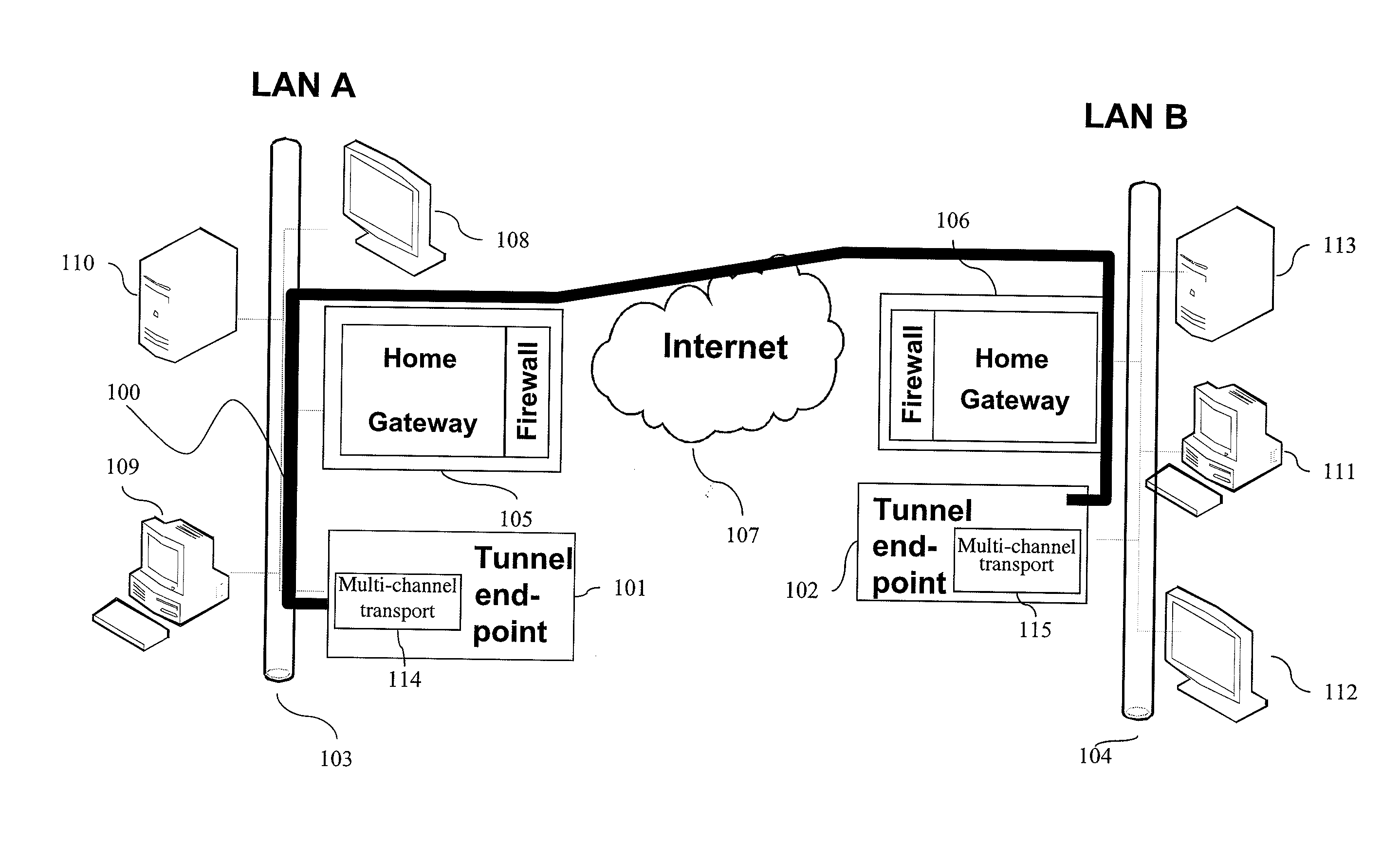
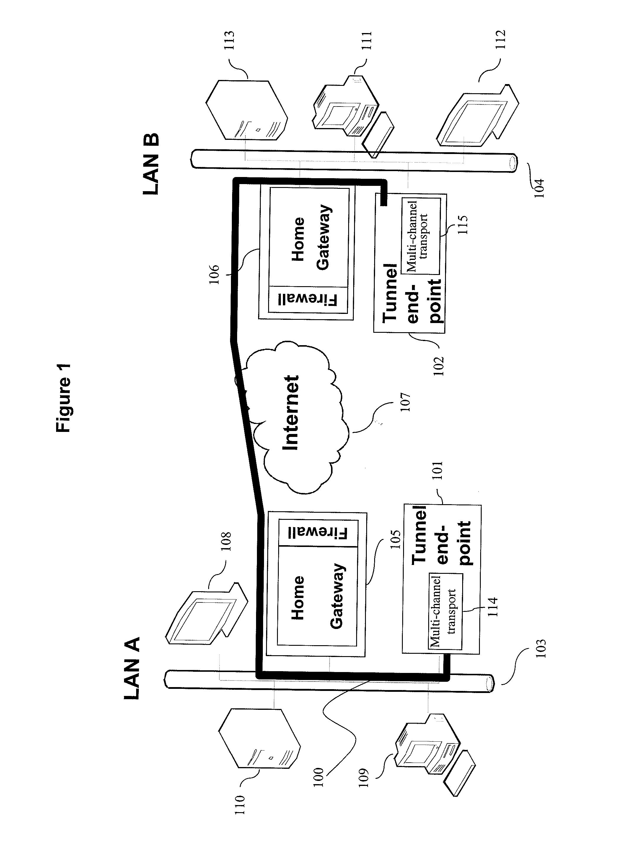
[0137]FIG. 1 provides a schematic illustration, according to a particular embodiment of the invention, of a virtual private network (VPN) implementing a tunnel 100 between a local tunnel end-point 101 and a remote tunnel end-point 102, through a communications network 107 (the Internet for example). This tunnel 100 connects a LAN network A 103 and another LAN network B 104. Each of the LANs 103 and 104 has a high-bit-rate Internet access apparatus of a home gateway type capable of integrating a firewall 105 and 106, PC type apparatuses 109 and 111, servers 110 and 113 for the storage and distribution of the digital media (of the audio, video and photo type) as well as digital media rendering apparatuses 108 and 112.

[0138]A tunnel end-point may be integrated into an audiovi...


PUM


Abstract

A method is disclosed for transmitting a multi-channel data stream comprising frames comprising a plurality of channels, the transmitting being done via a multi-transport tunnel from a first tunnel end-point to a second tunnel end-point, the multi-transport tunnel implementing at least one first carrier supporting a transport protocol with acknowledgement and at least one second carrier supporting a transport protocol without acknowledgement.More specifically, the invention proposes to introduce a delay in the sending of data (<<of high importance>>) via the first carrier as compared with the sending of data (<<of lesser importance>>) via the second carrier. Thus the invention guarantees the order of arrival of channels that are associated with a same piece of synchronization but are transmitted on distinct first and second carriers and come from the separation of a same multi-channel data frame.

Description

1. FIELD OF THE DISCLOSURE[0001]The field of the invention is that of communications networks.[0002]More specifically, the invention pertains to a technique for transmitting data packets (also called datagrams) on a tunnel going via a communications network. More specifically, the invention pertains to a technique for transmitting data packets (also called datagrams) on a multi-transport tunnel making it possible to preserve minimum latency while at the same time ensuring transmission of a multi-channel data stream with minimum guaranteed quality in the event of temporary congestion on the Internet.[0003]The democratization of high-bit-rate Internet on the one hand and the emergence of general consumer audiovisual equipment having network connectivity on the other hand are going to create new forms of behavior on the part of users. These new forms of behavior will undoubtedly involve the appearance of individuals belonging to groups of persons having common interests (leisure, famil...

Claims


Application Information

Patent Timeline
IPC IPC(8): H04L12/56H04J3/06G06F15/16
CPCH04L12/4633H04J3/06H04L45/00H04L12/66
Inventor VIGER, PASCALBARON, STEPHANE
Owner CANON KK
Why Eureka
Try Eureka