Jitter generation apparatus, device test system using the same, and jitter generation method

a jitter generation and apparatus technology, applied in the direction of line-transmission details, transmission monitoring, instruments, etc., can solve the problem of difficulty in accurately assigning a jitter at a modulation frequency as high as several ghz, and achieve the effect of not adding any jitter

Inactive Publication Date: 2010-06-17
ANRITSU CORP
View PDF4 Cites 13 Cited by
  • Summary
  • Abstract
  • Description
  • Claims
  • Application Information

AI Technical Summary

Benefits of technology

[0069]wherein when the second switching means (34) is switched to the third state as a result of switching control of the second switching means (34) to the third state based on the parameters set by the parameter setting means

Problems solved by technology

However, since the method of modulating a phase using the PLL circuit like in patent document 1 is limited by a frequency conversion response speed of an oscill

Method used


Image

  • Jitter generation apparatus, device test system using the same, and jitter generation method
  • Jitter generation apparatus, device test system using the same, and jitter generation method
  • Jitter generation apparatus, device test system using the same, and jitter generation method

Examples


first embodiment

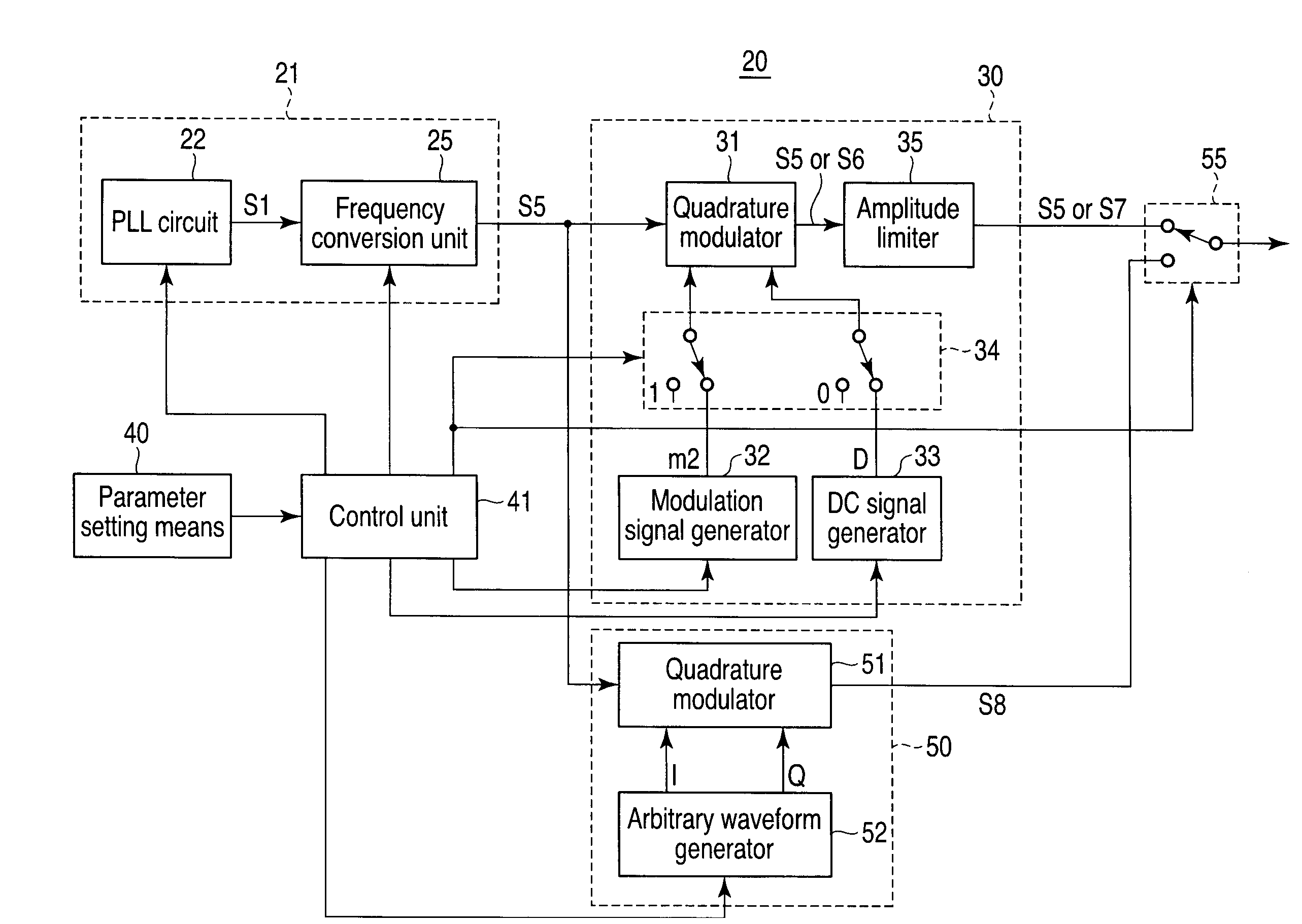
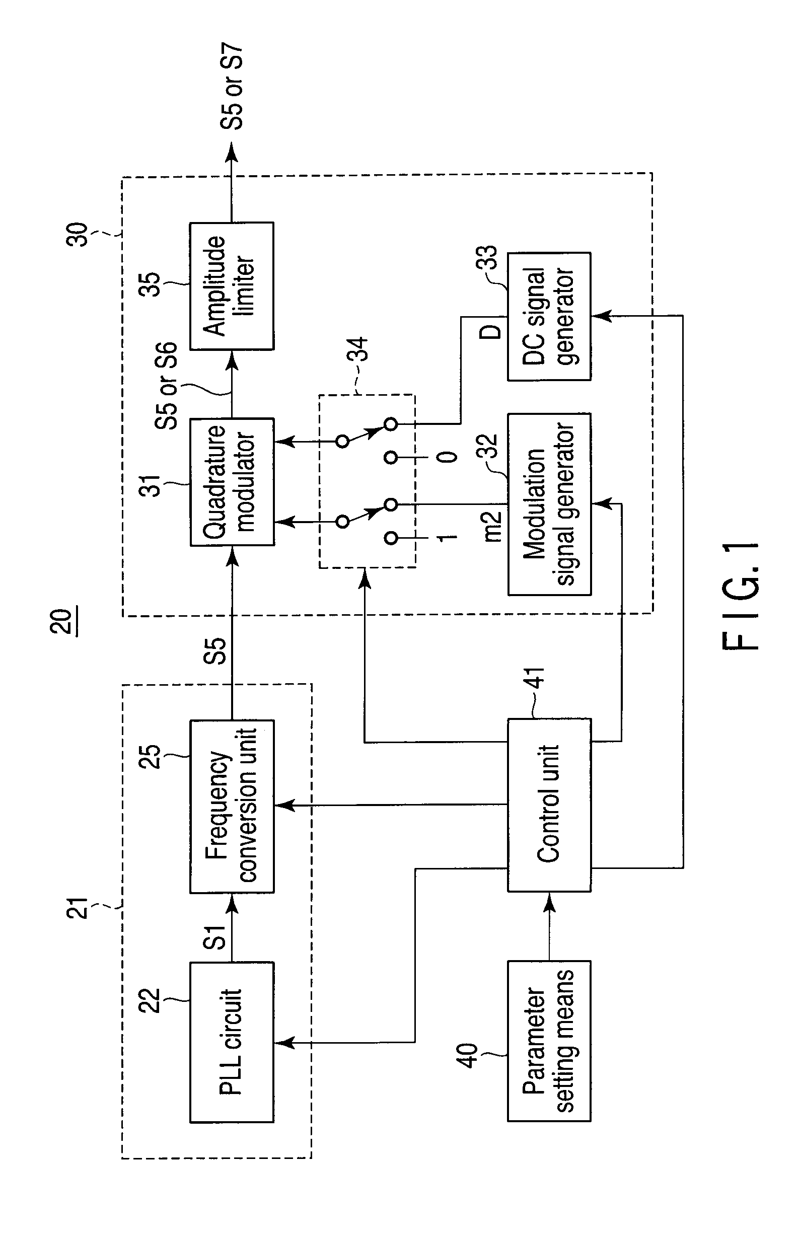
[0108]FIG. 1 is a block diagram for explaining the arrangement and operation of a jitter generation apparatus 20 and jitter generation method to which the first embodiment according to the present invention is applied.

[0109]The jitter generation apparatus 20 according to the first embodiment includes a first jitter generation unit 21, second jitter generation unit 30, parameter setting means 40, and control unit 41.

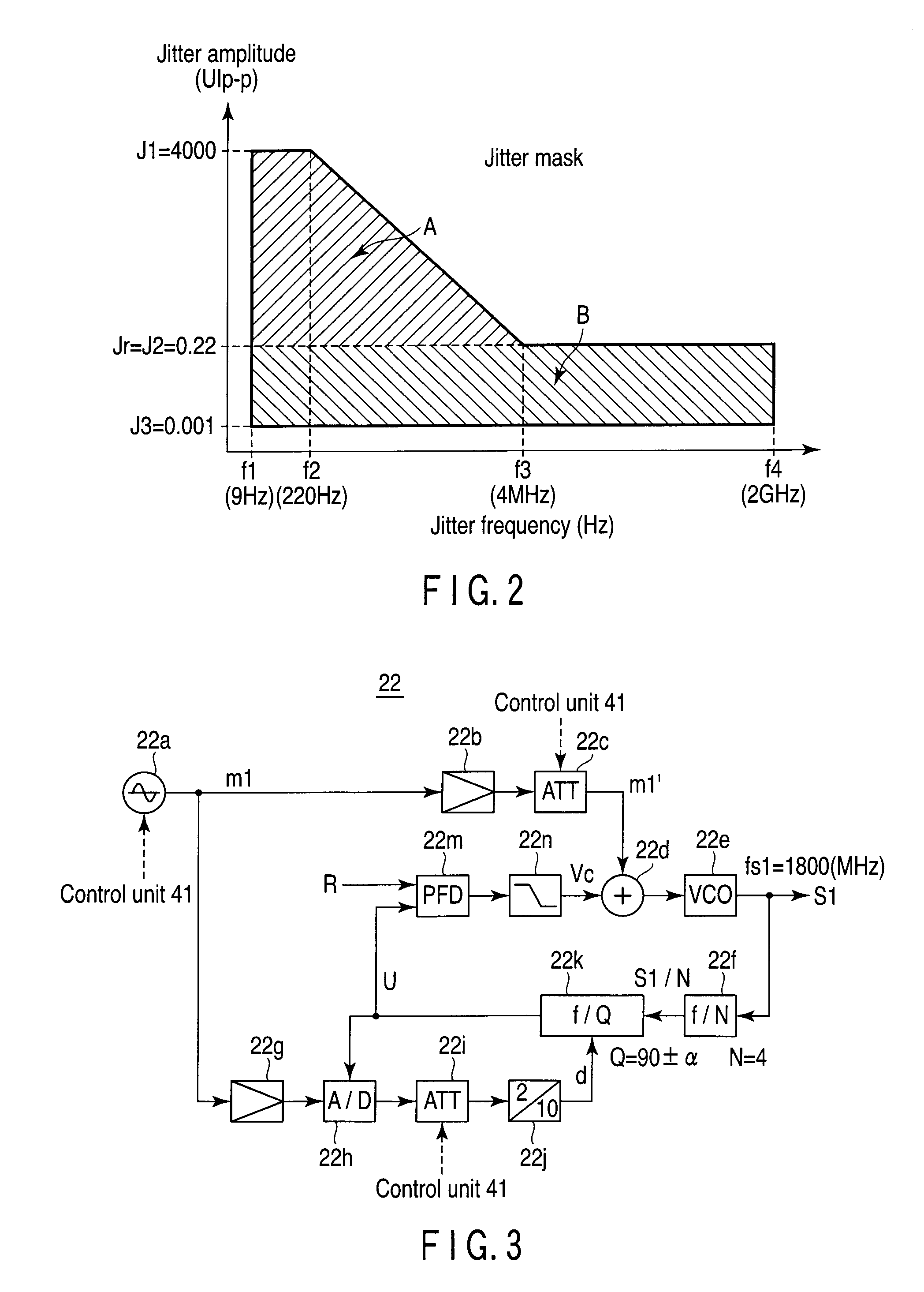
[0110]This jitter generation apparatus 20 generates and outputs a signal assigned with a jitter having an arbitrary jitter frequency and jitter amplitude, which are designated in a jitter mask shown in FIG. 2.

[0111]Note that the jitter mask shown in FIG. 2 has a constant jitter amplitude upper limit, i.e., 4000 (UIp−p)=J1 from a lower limit frequency f1 (e.g., 9 Hz) to a frequency f2 (e.g., 220 Hz) as in the aforementioned jitter mask shown in FIG. 17.

[0112]From the frequency f2 to a frequency f3 (e.g., 4 MHz), the jitter amplitude upper limit monotonically decreases from...

second embodiment

[0215]In this second embodiment, a first jitter region A may include a region in which a jitter frequency is less than f3 and a jitter amplitude is equal to or smaller than J2 and equal to or larger than J3 within a range of a jitter mask shown in, e.g., FIG. 12, and a first jitter generation unit 21 with a PLL arrangement may assign a jitter.

third embodiment

[0216]In the third embodiment, a range in which a jitter frequency ranges from f3 to a frequency f5 lower than an upper limit frequency may be set as a third jitter region C within a range of a jitter mask shown in FIG. 13, and jitter assignment for this third jitter region C may be done by a quadrature modulation method using a special waveform signal described in non-patent document 1 shown in FIG. 18.

[0217]In case of this third embodiment, as shown in FIG. 14, arbitrary waveform signals I and Q from an arbitrary waveform generator 38 can be supplied to a quadrature modulator 31 via a three-contact type switch 34′.

[0218]Note that since the arrangement in FIG. 14 other than that described above is the same as that of the jitter generation apparatus 20 shown in FIG. 1 of the first embodiment, the same reference numerals denote the same parts as in FIG. 1, and a detailed description thereof will not be repeated.

[0219]Note that a lower limit Jr of a jitter amplitude in a first jitter ...


PUM


Abstract

A jitter generation apparatus for applying a phase modulation to a PLL is controlled by a control unit so as to output a signal with the desired jitter based on a parameters. When a switching unit is switched to a first state, the control unit controls first and second level control units so that the desired jitter in which an amplitude of a first modulation signal matches the parameter is added to an output signal from a voltage controlled oscillator unit, and passes through a quadrature modulator. When the switching unit is switched to the second state, the control unit controls the first and second level control units so that a quadrature modulation is applied to a local signal, which is input to the quadrature modulator without adding any jitter to an output signal from the voltage controlled oscillator unit, and a quadrature-modulated local signal is output.

Description

CROSS REFERENCE TO RELATED APPLICATIONS[0001]This is a Continuation Application of PCT Application No. PCT / JP2008 / 067320, filed Sep. 25, 2008, which was published under PCT Article 21(2) in Japanese.[0002]This application is based upon and claims the benefit of priority from prior Japanese Patent Application No. 2007-253642, filed Sep. 28, 2007, the entire contents of which are incorporated herein by reference.BACKGROUND OF THE INVENTION[0003]1. Field of the Invention[0004]The present invention relates to a jitter generation apparatus, a device test system using the same, and a jitter generation method and, more particularly, to a jitter generation apparatus which adopts a technique for generating jitters over a broad band, a device test system using the same, and a jitter generation method.[0005]2. Description of the Related Art[0006]Measurement items for a data transmission system include jitter tolerance measurement that measures a tolerance level against a phase fluctuation (jit...

Claims


Application Information

Patent Timeline
IPC IPC(8): H04B17/00
CPCG01R31/31709H03C3/0966H03C3/095
Inventor YAGINUMA, KATSUYUKINISHIKOBARA, TADANORI
Owner ANRITSU CORP
Why Eureka
Try Eureka