Humidifier and fuel cell system

a fuel cell and humidifier technology, applied in the direction of lighting and heating apparatus, heating types, separation processes, etc., can solve the problems of water condensing into ice, damage to the hollow fiber membrane, and ice formed in the bottom of the case,

Active Publication Date: 2010-06-17
TOYOTA JIDOSHA KK
View PDF6 Cites 15 Cited by
  • Summary
  • Abstract
  • Description
  • Claims
  • Application Information

AI Technical Summary

Benefits of technology

[0022]Also according to this constitution, the water condenses or the condensed water becomes ice at a portion in the lower position of the case, and the portion can be located on the downstream side of the first gas and / or the second gas. In consequence, even when the first gas and / or the second gas flows from the higher position to the lower position, the condensed water or the ice can be inhibited from being directed to the steam permeable membrane by the flow. Therefore, the steam permeable membrane can be inhibited from being damaged.

Problems solved by technology

In consequence, the following problems might occur.
Specifically, during the halt of the fuel cell system in the low-temperature environment, if water remains in the oxidizing off gas inlet of the humidifier, the water condenses into ice.
Then, during the next startup of the fuel cell system, the ice might be flied by an introduced oxidizing off gas to come in contact with the hollow fiber membrane, and might damage the hollow fiber membrane.
Moreover, the ice formed in the bottom of the case might damage the hollow fiber membrane by the flow of an oxidizing gas.

Method used


Image

  • Humidifier and fuel cell system
  • Humidifier and fuel cell system
  • Humidifier and fuel cell system

Examples


first embodiment

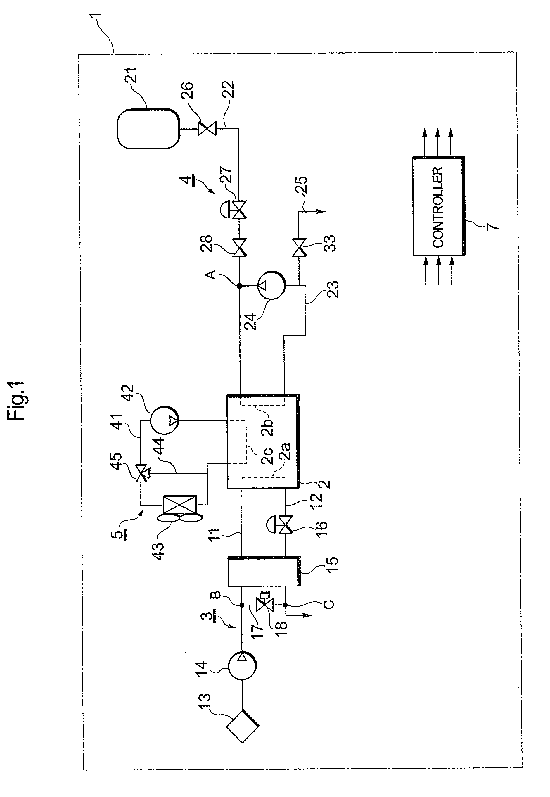
[0032]As shown in FIG. 1, a fuel cell system 1 includes a fuel cell 2, an oxidizing gas piping system 3, a fuel gas piping system 4, a refrigerant piping system 5, and a controller 7. The fuel cell system 1 can be mounted in a vehicle, but is, needless to say, applicable to not only the vehicle but also various mobile bodies (e.g., a ship, an airplane, a robot, etc.) and a stational power source.

[0033]The fuel cell 2 has a stack structure in which a large number of unit cells are stacked. Each unit cell of a solid polymer electrolyte type has an air electrode on one surface of an electrolyte, and a fuel electrode on the other surface thereof, and further has a pair of separators which sandwich the air electrode and the fuel electrode from both sides thereof. An oxidizing gas is fed to an oxidizing gas passage 2a of one of the separators, and a fuel gas is fed to a fuel gas passage 2b of the other separator. By an electrochemical reaction between the fed fuel gas and oxidizing gas, t...

second embodiment

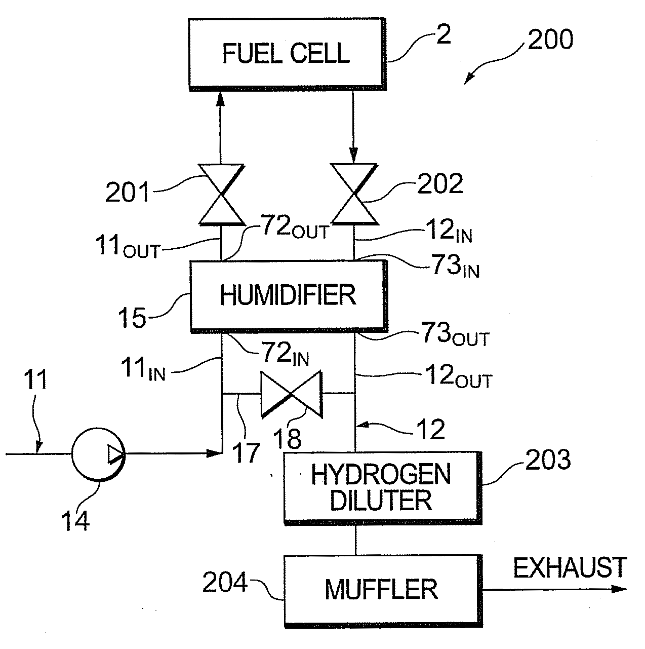
[0060]Next, with reference to FIGS. 5 to 8, a second embodiment of the present invention will be described mainly with respect to different respects. The embodiment is different from the first embodiment in that a positionally relation between each valve disposed around a humidifier 15 and the humidifier 15 is regulated.

[0061]As shown in FIG. 5, in a fuel cell system 200, the outlet pipe 11OUT and the inlet pipe 12IN are provided with shut valves 201, 202, respectively. Moreover, the bypass path 17 which connects the inlet pipe 11IN to the outlet pipe 12OUT is provided with the bypass valve 18 as described above. On the downstream side of the outlet pipe 12OUT, a hydrogen diluter 203 and a muffler 204 are provided. It is to be noted that the air cleaner 13 and the air regulation valve 16 in the fuel cell system 1 of the first embodiment are omitted from the drawing.

[0062]In the present embodiment, the shut valve 201, the shut valve 202 and the bypass valve 18 include valve bodies di...


PUM

PropertyMeasurementUnit
temperatureaaaaaaaaaa
inner diameteraaaaaaaaaa

Abstract

This specification discloses a humidifier that attains the inhibition of the damaging of a steam permeable membrane at low temperatures, and a fuel cell system. The humidifier has a steam permeable membrane therein. In the humidifier, an oxidizing gas and an oxidizing off gas with a humidity higher than that of the oxidizing gas are introduced, and the oxidizing gas is humidified by the oxidizing off gas via the steam permeable membrane. The steam permeable membrane is located at a position lower than an inlet for the oxidizing gas but higher than an outlet therefor. Further, the steam permeable membrane is located at a position lower than an inlet for the oxidizing off gas but higher than an outlet therefor.

Description

TECHNICAL FIELD [0001]The present invention relates to a humidifier and a fuel cell system. In particular, it relates to a humidifier which is effective for the improvement of a countermeasure against freezing in the winter, a cold district or the like.BACKGROUND ART [0002]A fuel cell system includes a fuel cell which generates a power by an electrochemical reaction between a fuel gas and an oxidizing gas. In a solid polymer type fuel cell, in order to increase the efficiency of the power generation thereof, an electrolyte film needs to be held in a humid state. This humid state is usually held by a humidifier which humidifies the fuel gas or the oxidizing gas.[0003]In a conventional humidifier, an internal humidifying system which performs water exchange between a highly humid oxidizing off gas and a lowly humid oxidizing gas is frequently employed. The oxidizing off gas is more humid than the oxidizing gas, because the oxidizing off gas discharged from an air electrode of the fuel...

Claims


Application Information

Patent Timeline
Patent Type & Authority Applications(United States)
IPC IPC(8): H01M8/06B01D63/02B01F3/02B01F23/10
CPCF24F2003/1435H01M8/04126Y02E60/50H01M8/04149H01M2008/1095H01M8/04141F24F6/04H01M8/04
Inventor KANAZAWA, HIROFUMI
Owner TOYOTA JIDOSHA KK
Why Eureka
Try Eureka