
Power state dependent wake-up alarm

a technology of wake-up alarm and power state, applied in the field of power state dependent wake-up alarm, can solve the problems of mobile device not transitioning back to sleep mode, device to wake up, and rtc alarm may expire, so as to achieve different wake-up behavior and improve the operation of computing devices

Active Publication Date: 2010-06-17
MICROSOFT TECH LICENSING LLC
View PDF14 Cites 65 Cited by
  • Summary
  • Abstract
  • Description
  • Claims
  • Application Information

AI Technical Summary

Benefits of technology

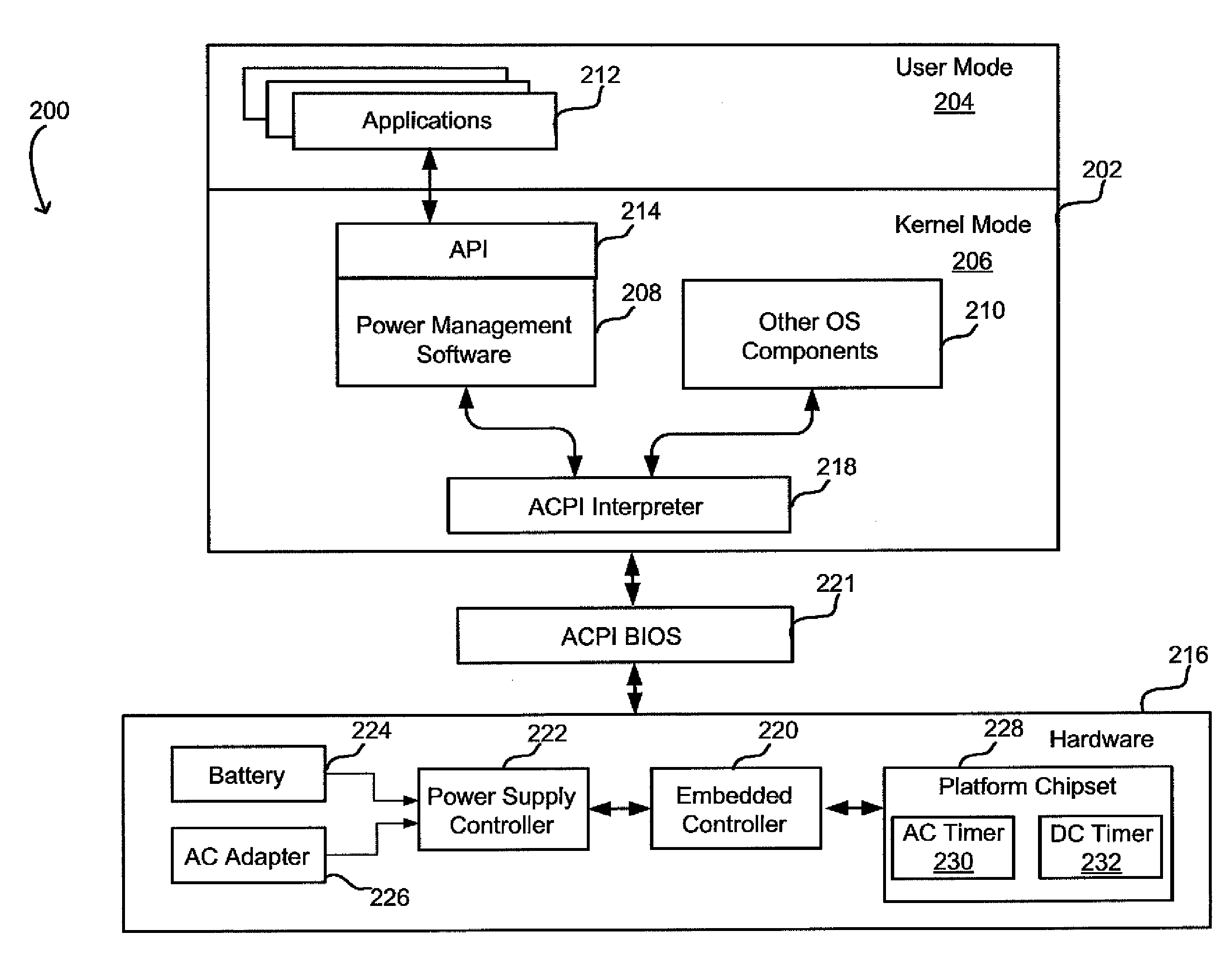
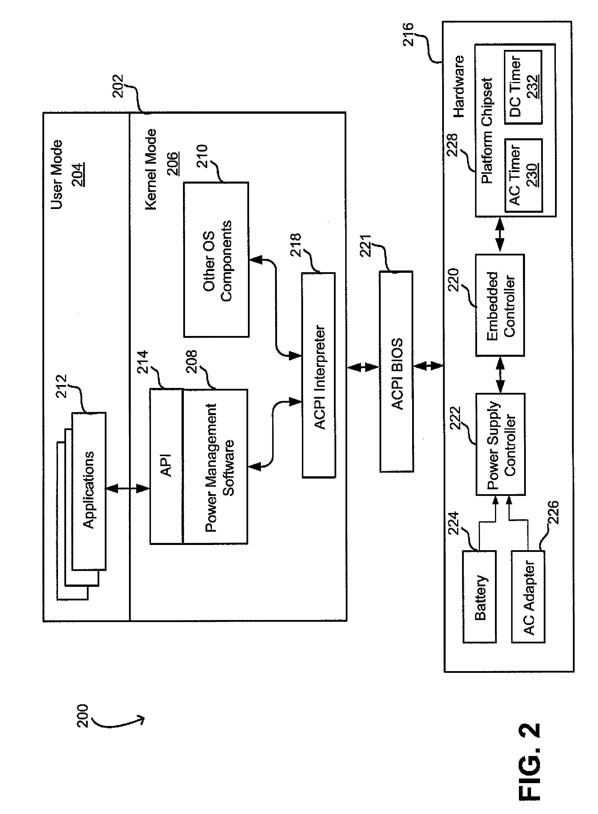
The invention is about improving the operation of a computing device by making it conditional on its power state. This allows the device to have different wake-up behaviors depending on whether it is operating on AC or DC power. The control of this process can be done by accepting requests for establishing wake-up behavior based on the current power state of the device. The invention also utilizes timers to wake up the device based on its current power state, which can save battery power. The invention provides separate timers for AC and DC power modes and monitors the power source being used by the device. Overall, the invention allows for better control over the device's wake-up behavior and helps to save battery power.

Problems solved by technology

Also, the device may have a timer that causes the device to wake up when the timer expires.
As a result, the RTC alarm may expire when a mobile device operating on the battery is in a thermally constrained environment, such as an overhead compartment on an airplane or in a carrying bag.
In such scenarios, after waking up, the mobile device does not transition back to a sleep mode and may overheat.
Overheating can degrade performance and can damage underlying hardware.
Moreover, a user experience may be compromised because the battery may discharge sooner than expected by a user who is then not able to use the computer device.

Method used


Image

  • Power state dependent wake-up alarm
  • Power state dependent wake-up alarm
  • Power state dependent wake-up alarm

Examples


Embodiment Construction

[0023]The inventors have recognized and appreciated limitations of known power management systems that prevent a hardware alarm, such as an RTC alarm, from waking the device from a sleep mode when the device operates on a DC battery power. A limitation of such an approach is the consequence that the device may not wake up to transition from a low to a lower power mode, which is desired to save the battery power. Therefore, a computing device situated in a possibly constrained environment may not transition from one low power mode to another, which increases system power consumption thus adversely affecting the battery life. More generally, such approach limits the ability of the device to reliably provide functionality based on timed wake-up events. For example, a device cannot be used as an alarm clock or to provide other functionality requiring automatic wake up of the computing device operating on a battery.

[0024]The inventors have appreciated that a timer determining wake-up beh...


PUM


Abstract

A method of operating a computing device to allow events to be conditionally executed based on a power state of the device at the time of execution of the events. Conditional execution may be implemented using multiple timers, each associated with a power state. A timer such as an “AC timer” or a “DC timer” associated with a respective power state may be used to wake up the device when, upon expiration, or time-out, of the timer, a current power state of the device and the power state associated with the timer match. An Advanced Configuration Power Interface (ACPI) may be employed to abstract implementation of the timers from underlying hardware of the device. The operating system and software applications may request establishing wake-up behavior of the device as commands to program conditional events, which may then be translated into commands to embedded controller to set the timers.

Description

BACKGROUND[0001]Computer devices conventionally operate using an alternating current (AC) power source. A mobile computer device, such as a laptop, additionally may operate with power supplied by a battery providing direct current (DC) power. Regardless of whether a device is using AC or DC power, it may implement one or more “sleep” modes in order to save power.[0002]In a sleep mode, one or more components of the device may be disabled. For example, a screen or other display device may be turned off to implement a sleep mode. Other components such as a processor or wireless transceiver may be shut down. In some instances, devices implement different sleep levels, with successively more components turned off in each deeper sleep mode.[0003]A device may enter a sleep mode in one or more ways. If a device has not been in use for a certain time, it may automatically enter a sleep mode. The device may also enter a sleep mode upon a user input (e.g., pressing of a pause or standby button...

Claims


Application Information

Patent Timeline
Patent Type & Authority Applications(United States)
IPC IPC(8): G06F1/00
CPCG06F1/3203
Inventor STEMEN, PATRICK L.LIAW, TIMOTHY W.JUDGE, NICHOLAS S.PIERCE, TONYTAO, LIBO
Owner MICROSOFT TECH LICENSING LLC
Learn More