System and method for employing signoff-quality timing analysis information concurrently in multiple scenarios to reduce leakage power in an electronic circuit and electronic design automation tool incorporating the same

a technology of signoff quality and timing analysis, applied in the field of integrated circuits (ic), can solve the problems of circuits that cannot operate properly, circuits that cannot meet the requirements of operation, circuits that may have to operate at a slower speed,

Inactive Publication Date: 2010-06-17
AVAGO TECH WIRELESS IP SINGAPORE PTE
View PDF28 Cites 28 Cited by
  • Summary
  • Abstract
  • Description
  • Claims
  • Application Information

AI Technical Summary

Benefits of technology

[0006]To address the above-discussed deficiencies of the prior art, one aspect of the invention provides a timing signoff tool. In one embodiment, the timing signoff tool includes: (1) a power recovery module configured to carry out an instance of an initial power recovery process in each of multiple scenarios concurrently, the initial power recovery process including making first conditional replacements of cells in at least one path in a circuit design with lower leakage cells and estimating a delay and a

Problems solved by technology

Power consumption is a concern in most circuit designs, particularly those that are to be battery-powered.
Timing is a major concern in all IC designs, because circuits will not operate properly unless signals can propagate properly through them.
If propagation time is inadequate, critical paths in the circuit may have to be modified, or the circuit may have to operate at a slower speed.
Power and timing objectives are often at odds; faster devices usually require more power

Method used


Image

  • System and method for employing signoff-quality timing analysis information concurrently in multiple scenarios to reduce leakage power in an electronic circuit and electronic design automation tool incorporating the same
  • System and method for employing signoff-quality timing analysis information concurrently in multiple scenarios to reduce leakage power in an electronic circuit and electronic design automation tool incorporating the same
  • System and method for employing signoff-quality timing analysis information concurrently in multiple scenarios to reduce leakage power in an electronic circuit and electronic design automation tool incorporating the same

Examples


Embodiment Construction

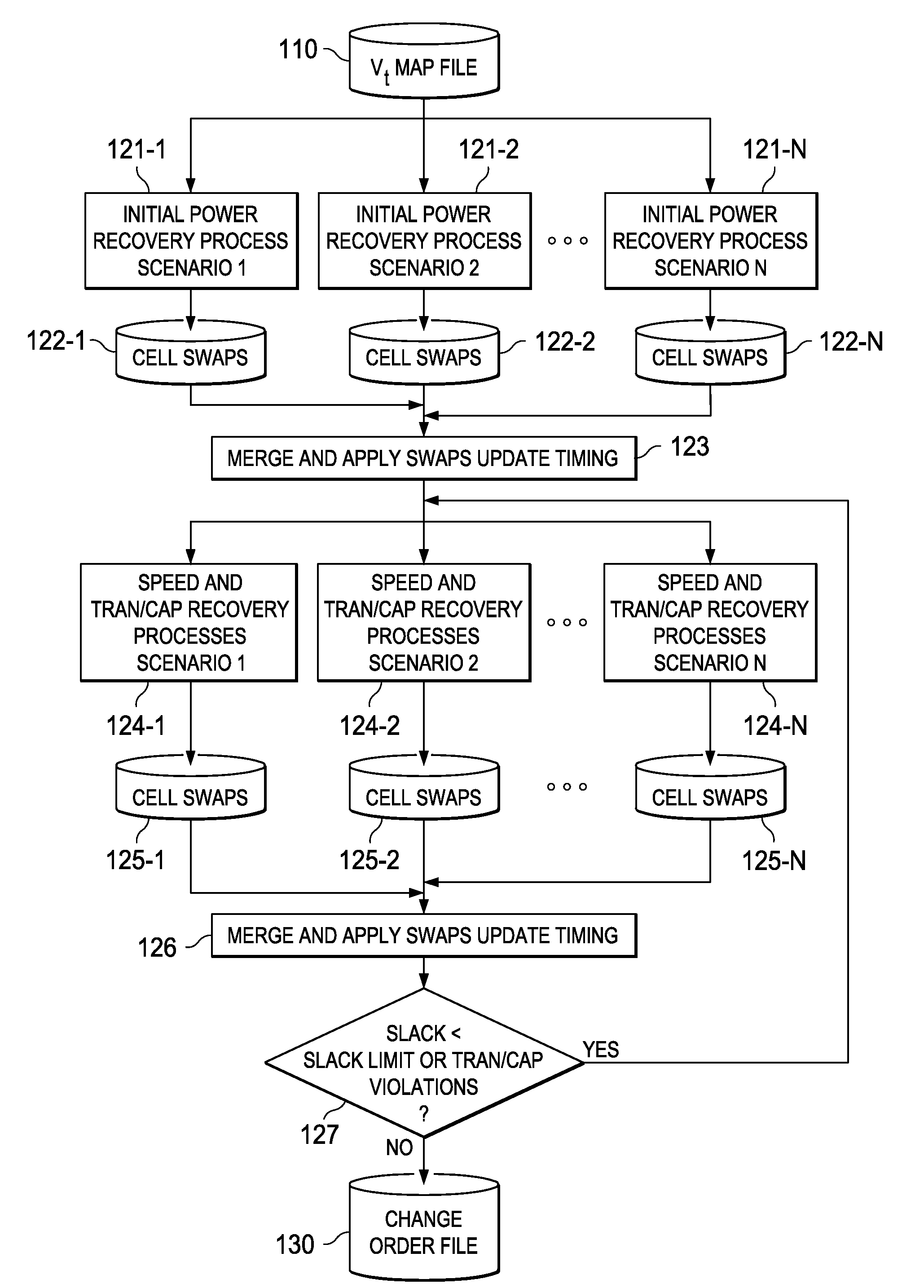
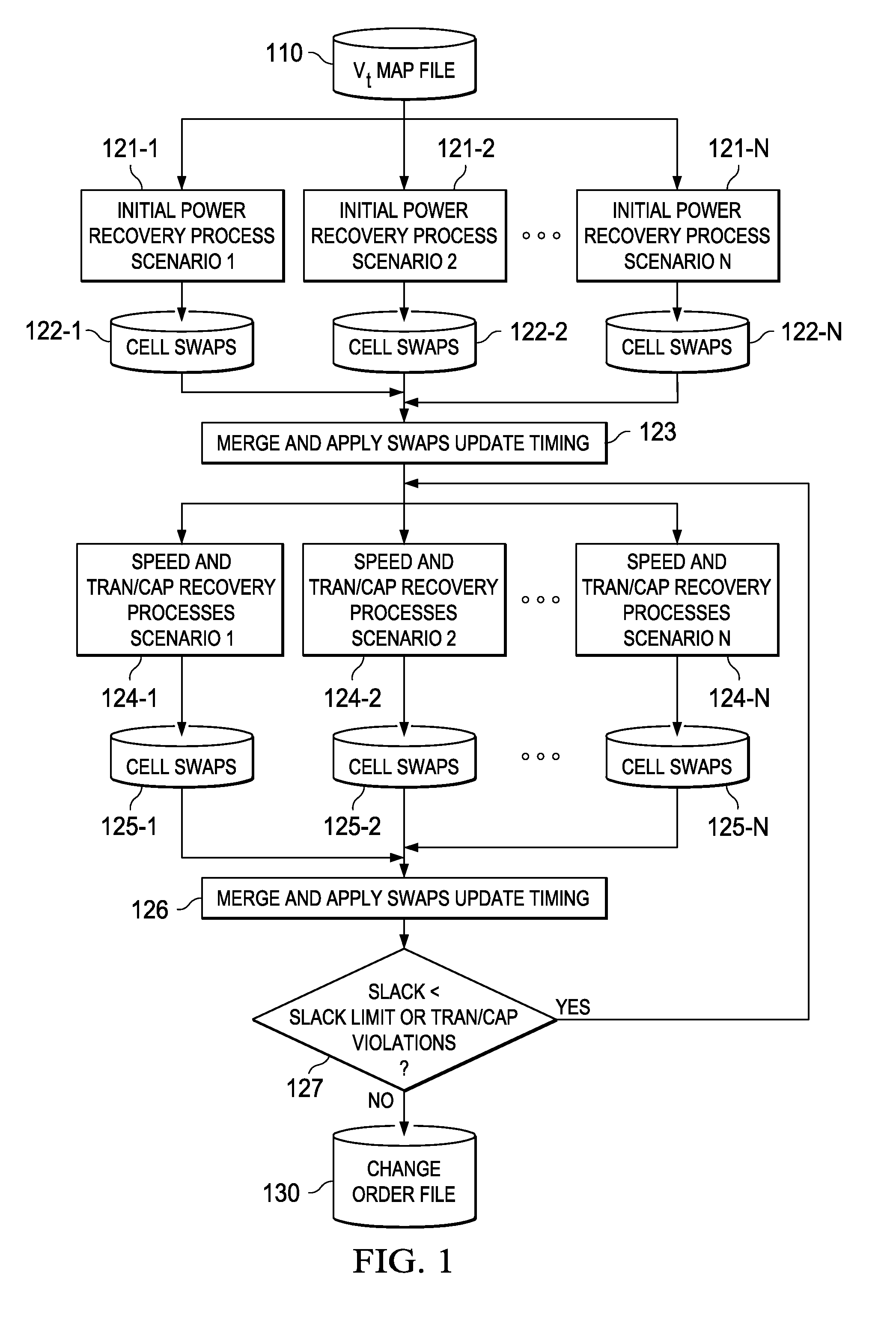
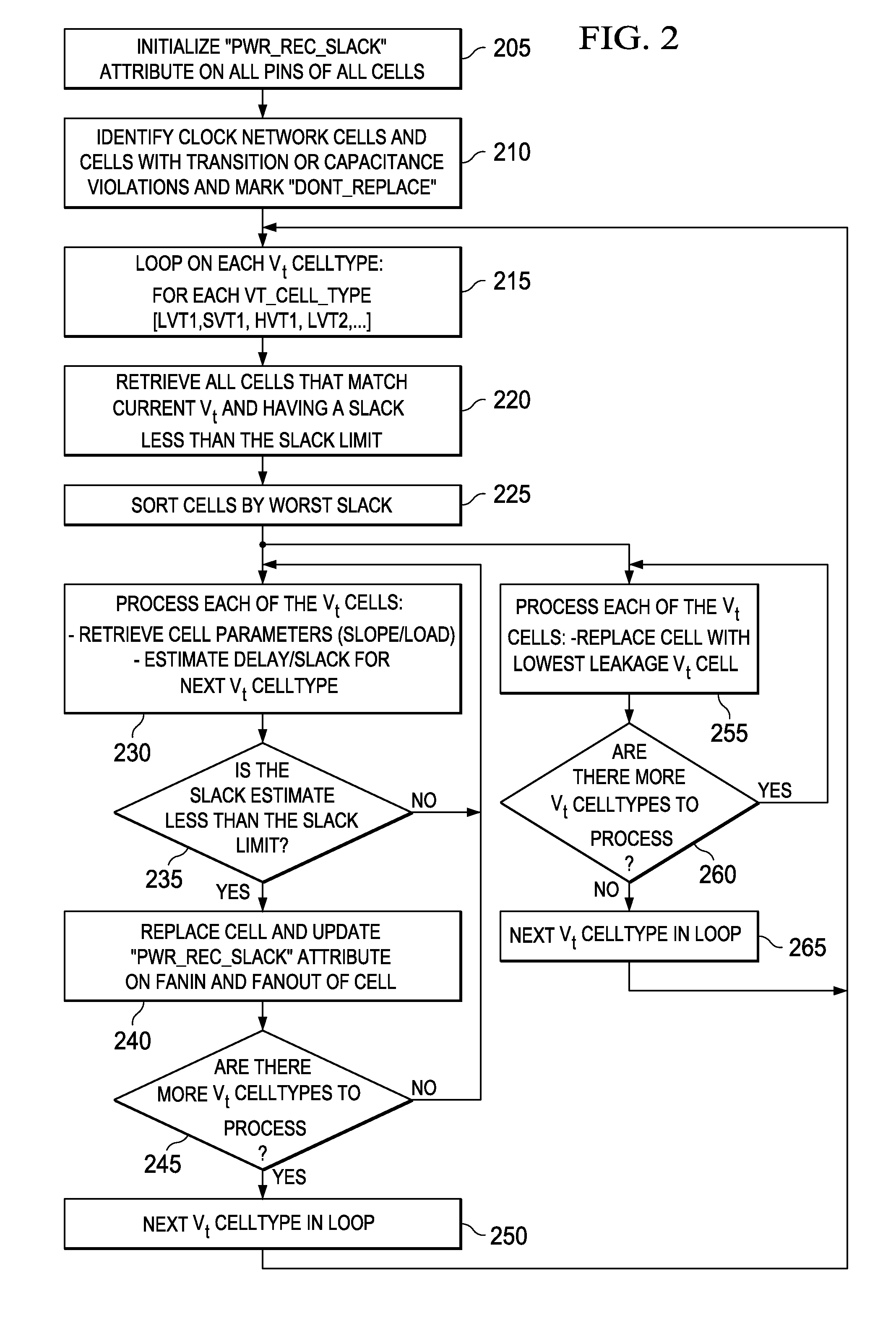
[0015]Described herein are various embodiments of an EDA tool and method for employing signoff-quality timing analysis information to reduce leakage power in an electronic circuit, such as an IC. One embodiment of the method, referred to herein as a leakage power recovery method, is carried out during timing signoff to achieve improved, perhaps optimal, leakage power levels while preserving the timing performance of the circuit design. The leakage power recovery method analyzes the timing of a circuit design and replaces higher leakage cells with lower leakage cells on paths with a positive timing margin. The lower leakage cells are inherently slower, but the leakage power recovery method determines how many lower leakage cells can be used without adversely affecting performance targets.

[0016]Unlike the conventional combined optimization tool described above, the novel system and method described herein operate with an accurate representation of the finished circuit design such that...


PUM


Abstract

A leakage power recovery system and method, and a electronic design automation (EDA) tool incorporating either or both of the system and the method. In one embodiment, the timing signoff tool includes: (1) a power recovery module configured to carry out an instance of an initial power recovery process in each of multiple scenarios concurrently, the initial power recovery process including making first conditional replacements of cells in at least one path in a circuit design with lower leakage cells and estimating a delay and a slack of the at least one path based on the first conditional replacements and (2) a speed recovery module associated with the power recovery module and configured to carry out a speed recovery process in each of the multiple scenarios concurrently, the speed recovery process including determining whether the first conditional replacements cause a timing violation with respect to the at least one path and making second conditional replacements with higher leakage cells until the timing violation is removed.

Description

CROSS-REFERENCE TO RELATED APPLICATION[0001]This application is related to U.S. patent application Ser. No. 12 / 198,030, filed by Zahn on Aug. 25, 2008, entitled “System and Method for Employing Signoff-Quality Timing Analysis Information to Reduce Leakage Power in an Electronic Circuit and Electronic Design Automation Tool Incorporating the Same,” commonly assigned with this application and incorporated herein by reference.TECHNICAL FIELD[0002]The invention is directed, in general, to integrated circuits (ICs) and, more specifically, to a system and method for employing signoff-quality timing analysis information concurrently in multiple scenarios to reduce leakage power in an electronic circuit, particularly an IC, and an electronic design automation (EDA) tool incorporating the same.BACKGROUND[0003]Power consumption is a concern in most circuit designs, particularly those that are to be battery-powered. Circuit designs should achieve the lowest possible power consumption while ach...

Claims


Application Information

Patent Timeline
IPC IPC(8): G06F17/50
CPCG06F2217/78G06F17/5045G06F30/30G06F2119/06
Inventor ZAHN, BRUCE E.
Owner AVAGO TECH WIRELESS IP SINGAPORE PTE
Why Eureka
Try Eureka