Fin field effect transistor having low leakage current and method of manufacturing the finfet
a technology of field effect transistor and finfet, which is applied in the direction of transistors, electrical devices, semiconductor devices, etc., can solve the problems of inability to relatively shorten the depth of source/drain, drain current increase in an off state, and reduce the size of cell devices, etc., to achieve low leakage current
- Summary
- Abstract
- Description
- Claims
- Application Information
AI Technical Summary
Benefits of technology
Problems solved by technology
Method used
Image
Examples
second embodiment
Hereinafter, a FinFET having low leakage current according to a second embodiment of the present invention will be described in detail. FIG. 8a is a perspective view illustrating the FinFET according to the second embodiment of the present invention, and FIG. 8b is a cross-sectional view taken along line A-A′ of FIG. 8a. Referring to FIG. 8, the FinFET according to the second embodiment includes a substrate 810, a fence-shaped body 820, a gate insulating layer 830, a first insulating layer 832, a nitride layer 840, a second insulating layer 850, a first gate electrode 870, a second gate electrode 880, and source / drain regions 890 and 892. A description of components of the FinFET according to the second embodiment that are the same as those according to the first embodiment is omitted for the convenience of description.
[0101]The second insulating layer 850 is a device isolating layer for electrically isolating a corresponding device from an adjacent device and is also called a field...
third embodiment
[0105]Hereinafter, a structure of a FinFET having low leakage current according to a third embodiment of the present invention will be described in detail with reference to FIG. 10. Components of the FinFET according to the current embodiment excluding a gate electrode are the same as those according to the first embodiment, so that a detailed description thereof is omitted.
[0106]FIG. 10a is a perspective view and FIG. 10b is a top plan view illustrating the FinFET 101 according to the third embodiment of the present invention. Referring to FIG. 10, the FinFET according to the third embodiment of the present invention includes second gate electrodes 1080 and 1082 having low work functions disposed at both side surfaces of a first gate electrode 1070 having a high work function. In the aforementioned structure of the gate electrode, a drain region and a source region overlap with the second gate electrodes 1080 and 1082 having low work functions. Accordingly, GIDL can be reduced. How...
fourth embodiment
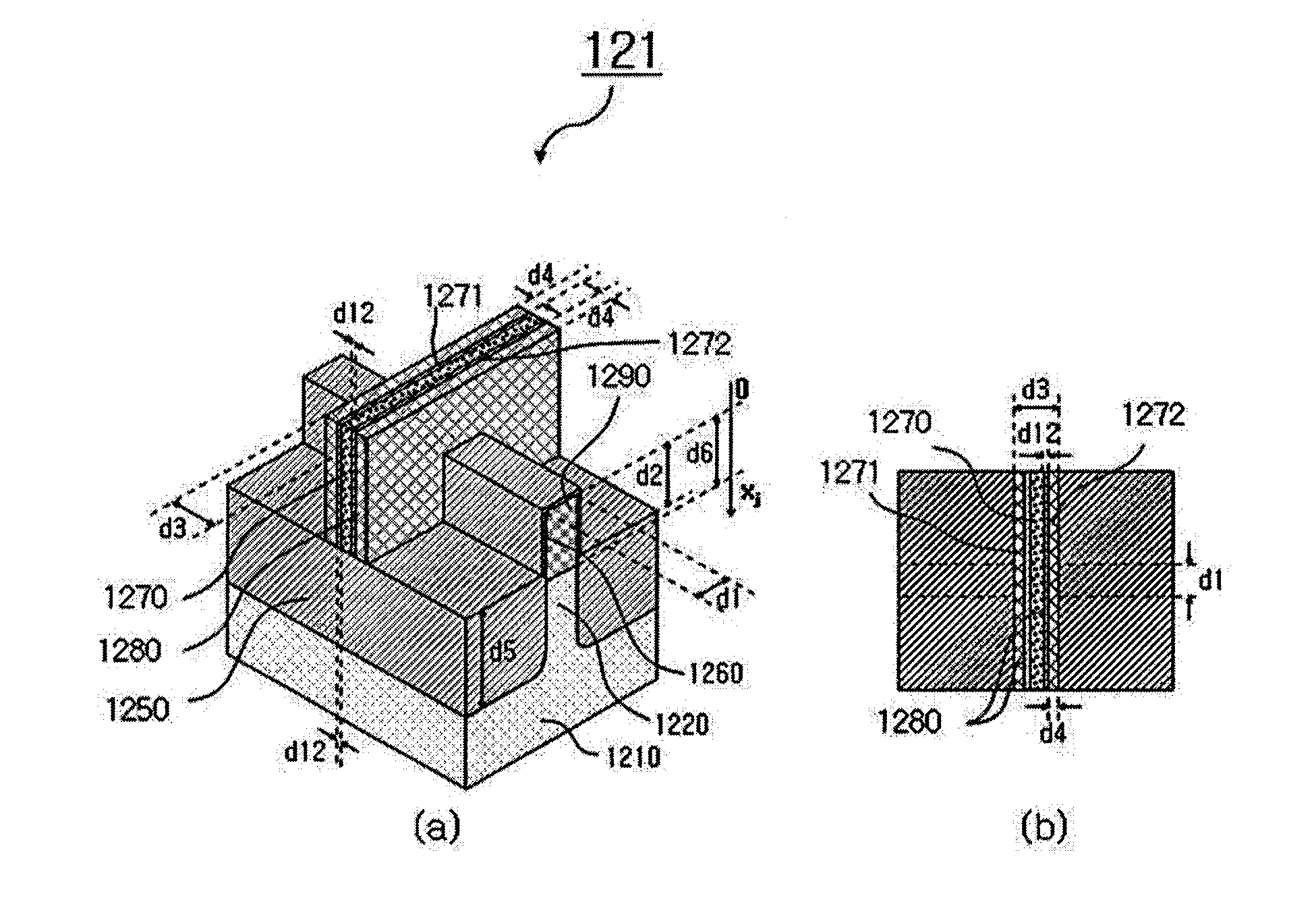
[0108]Hereinafter, a structure of a FinFET 111 having low leakage current according to a fourth embodiment of the present invention will be described in detail with reference to FIG. 11. Components of the FinFET according to the current embodiment excluding a gate electrode are the same as those according to the first embodiment, so that a detailed description thereof is omitted.
[0109]FIG. 11a is a perspective view and FIG. 11b is a top plan view illustrating the FinFET according to the fourth embodiment of the present invention. Referring to FIG. 11, the FinFET according to the fourth embodiment of the present invention further includes an isolation insulating layer 1182 for electric isolation provided between a first gate electrode 1170 having a high work function and a second gate electrode 1180 having a low work function. A thickness d12 of the added isolation insulating layer 1182 ranges from 0.5 to 10 nm.
[0110]The structure of the gate electrode according to the fourth embodim...
PUM
 Abstract
Description
Claims
Application Information
 - R&D
- Intellectual Property
- Life Sciences
- Materials
- Tech Scout
- Unparalleled Data Quality
- Higher Quality Content
- 60% Fewer Hallucinations
Browse by: Latest US Patents, China's latest patents, Technical Efficacy Thesaurus, Application Domain, Technology Topic, Popular Technical Reports.
© 2025 PatSnap. All rights reserved.Legal|Privacy policy|Modern Slavery Act Transparency Statement|Sitemap|About US| Contact US: help@patsnap.com


