Apparatus and method for multi-dimensional gas chromatography

Active Publication Date: 2010-06-24
SCHLUMBERGER TECH CORP
View PDF16 Cites 26 Cited by
  • Summary
  • Abstract
  • Description
  • Claims
  • Application Information

AI Technical Summary

Benefits of technology

[0012]Therefore, there is a need for a method and apparatus (which also may be referred to herein as a “system”) that addresses the above and other problems. The above and other needs and problems are addressed by the exemplary embodiments of the present invention, which provide a method and apparatus, including a valve based modulation technique for two-dimensional gas chromatography (e.g., GCXGC, GC-GC, or 2DGC) and which has several advantages. In combination with dual high-pressure detectors, significant improvements in system performance are possible. A traditional first dimension GC separation is performed and the effluent exits into a sampling valve. The valve is designed such that it has two positions, both of which allow for collection of an effluent sample and injection of a previously collected sample. The valve is cycled between the two positions, such that collected samples are introduced into each of two secondary columns in an alternating fashion. Advantageously, this allows for a two-fold i

Problems solved by technology

However, with most modulators the flow from the first and second dimension columns are related, and therefore independently optimizing the flow conditions of the first and second dimensions is difficult.
However, they do not offer the peak capacity of GCXGC.
However, typical thermal modulators require that the carrier gas flow from the first dimension also be used for the second dimension, which can make it difficult to optimize flow conditions for both separation stages.
A potential disadvantage to thermal modulators is the vapor pressure range limitation of most thermal cycling systems.
For example, for virtually all

Method used


Image

  • Apparatus and method for multi-dimensional gas chromatography
  • Apparatus and method for multi-dimensional gas chromatography
  • Apparatus and method for multi-dimensional gas chromatography

Examples


Example

[0035]Various embodiments and aspects of the invention will now be described in detail with reference to the accompanying figures. The terminology and phraseology used herein is solely used for descriptive purposes and should not be construed as limiting in scope. Language such as “including,”“comprising,”“having,”“containing,” or “involving,” and variations thereof, is intended to be broad and encompass the subject matter listed thereafter, equivalents, and additional subject matter not recited.

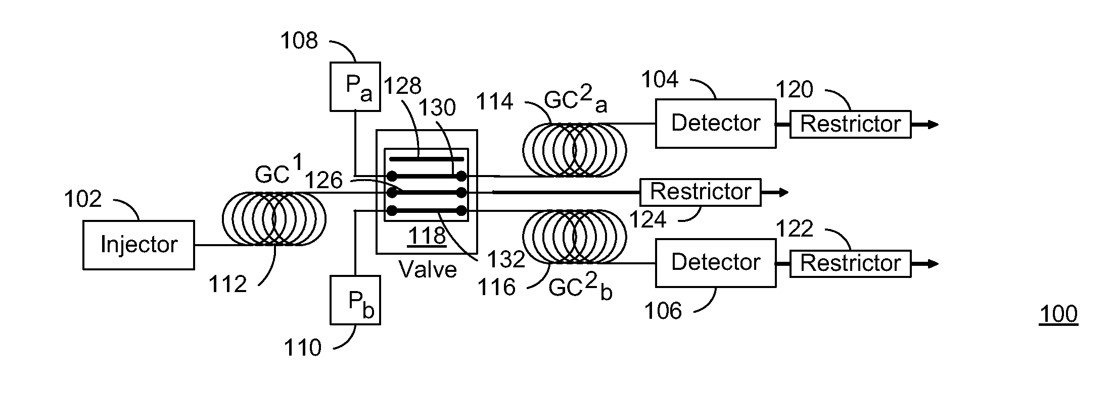
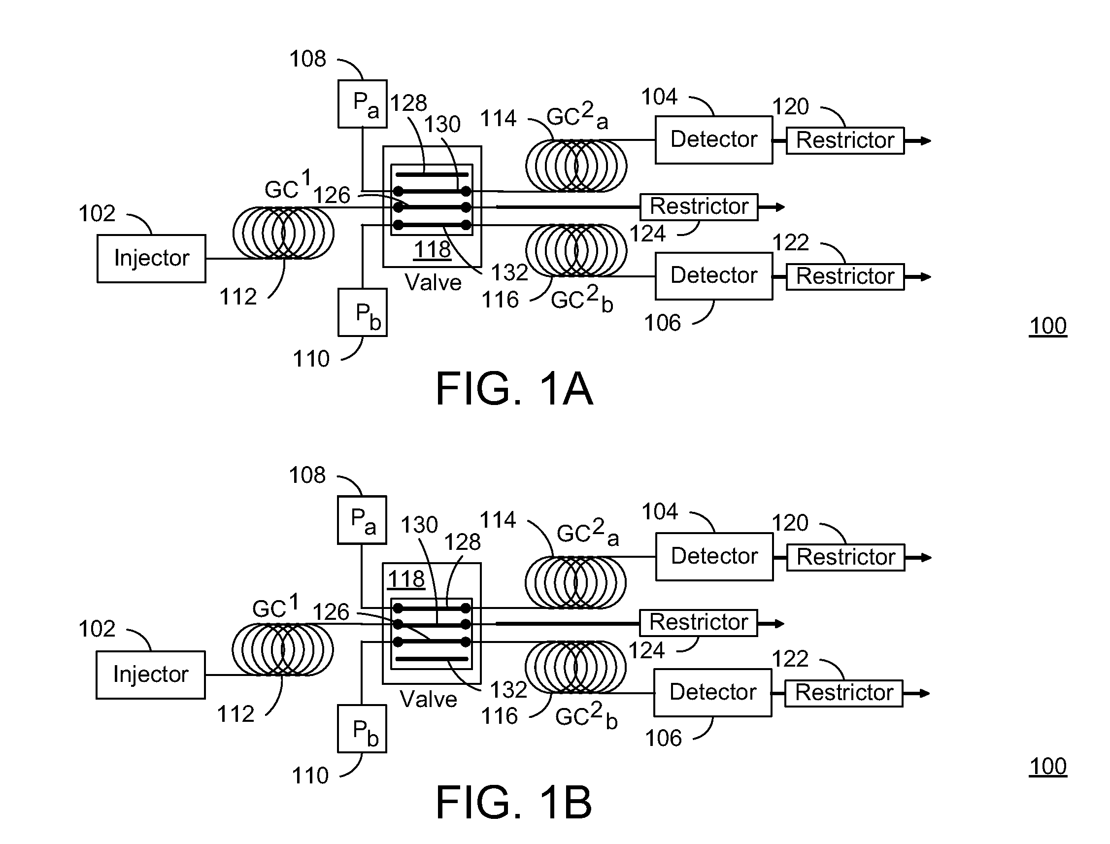
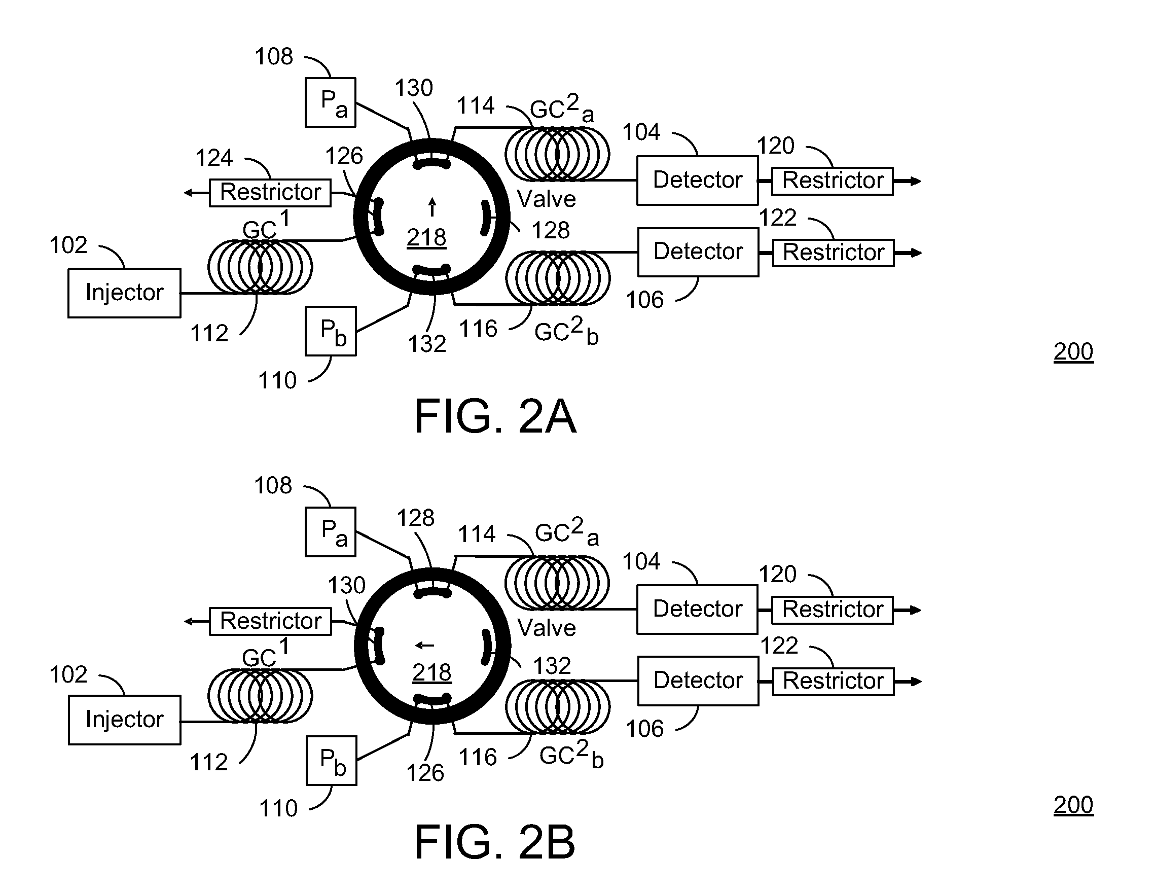
[0036]Referring now to the drawings, wherein like reference numerals designate identical or corresponding parts throughout the several views, and more particularly to FIGS. 1-3 thereof, there are illustrated exemplary valve based modulation systems 100-300 that can be used for two-dimensional gas chromatography (GC) (GCXGC, GC-GC, or 2DGC). In FIGS. 1-3, the respective exemplary valve modulation systems 100-300 for two-dimensional gas chromatography include injectors 102, detectors 104 and 1...


PUM

PropertyMeasurementUnit
Timeaaaaaaaaaa
Volumeaaaaaaaaaa
Volumetric flow rateaaaaaaaaaa

Abstract

A method and apparatus for two-dimensional gas chromatography (GC), including a valve having first and second positions (P1, and P2), and first through fourth sample flow paths (FP1-FP4). In P1, a first gas sample is collected from a first dimension GC column via FP1, a first pressure source and a first, second dimension GC column are connected via FP2, a second pressure source and a second, second dimension GC column are connected via FP3, and FP4 is disconnected. In P2, the first sample in FP1 is introduced to the second, second dimension GC column via FP1, with aid of the second pressure source, a second gas sample is collected from the first dimension GC column via FP2, the first pressure source and the first, second dimension GC column via FP4 are connected, and FP3 is disconnected.

Description

CROSS-REFERENCE TO RELATED APPLICATION[0001]The present application is based on and claims priority to U.S. Provisional Patent Application No. 61 / 140,094, filed Dec. 23, 2008.TECHNICAL FIELD[0002]The present invention generally relates to gas chromatography, and more particularly to valve based modulation for comprehensive two-dimensional gas chromatography.STATE OF THE ART[0003]Multi-dimensional gas chromatography is an advanced field where multiple gas-phase separations are performed in series on a single sample. A modulator is used to periodically collect and inject effluent from each separation column into a subsequent separation column. Typically, the modulator is actuated according to a constant schedule. It is necessary to tune the separation of each subsequent stage, such that an entire separation is completed within each cycle of the modulator. This sequence allows for independent determination of the retention time of each component on each dimension of the separation. Abs...

Claims


Application Information

Patent Timeline
IPC IPC(8): G01N25/18B01D53/02
CPCG01N30/463G01N2030/025G01N30/465
Inventor LAMBERTUS, GORDONSTEINECKER, WILLIAM
Owner SCHLUMBERGER TECH CORP
Why Eureka
Try Eureka