Caliper Logging Using Circumferentially Spaced and/or Angled Transducer Elements

a transducer element and circumferential space technology, applied in the field of downhole tools, can solve the problems of reducing ultrasonic energy at the receiver, blind spots at which the reflected wave is undetected by the sensor, and can have significant negative consequences, so as to improve the quality and reliability of lwd data, reduce or even eliminate blind spots, and improve borehole coverage

Active Publication Date: 2010-06-24
SCHLUMBERGER TECH CORP
View PDF101 Cites 27 Cited by
  • Summary
  • Abstract
  • Description
  • Claims
  • Application Information

AI Technical Summary

Benefits of technology

[0009]Exemplary embodiments of the present invention advantageously provide several technical advantages. For example, exemplary embodiments of the invention may improve borehole coverage and data quality and reliability in LWD caliper logging. In particular, th

Problems solved by technology

In these operations the transmitted ultrasonic waves are sometimes incident on the borehole wall at a non-normal (oblique) angle, which can result in reduced ultrasonic energy at the receiver.
In some cases there may be blind spots at which t

Method used


Image

  • Caliper Logging Using Circumferentially Spaced and/or Angled Transducer Elements
  • Caliper Logging Using Circumferentially Spaced and/or Angled Transducer Elements
  • Caliper Logging Using Circumferentially Spaced and/or Angled Transducer Elements

Examples


Embodiment Construction

[0021]Referring first to FIGS. 1 through 6, it will be understood that features or aspects of the embodiments illustrated may be shown from various views. Where such features or aspects are common to particular views, they are labeled using the same reference numeral. Thus, a feature or aspect labeled with a particular reference numeral on one view in FIGS. 1 through 6 may be described herein with respect to that reference numeral shown on other views. It will all be appreciated that FIGS. 1-6 are schematic in nature and are therefore not drawn to scale.

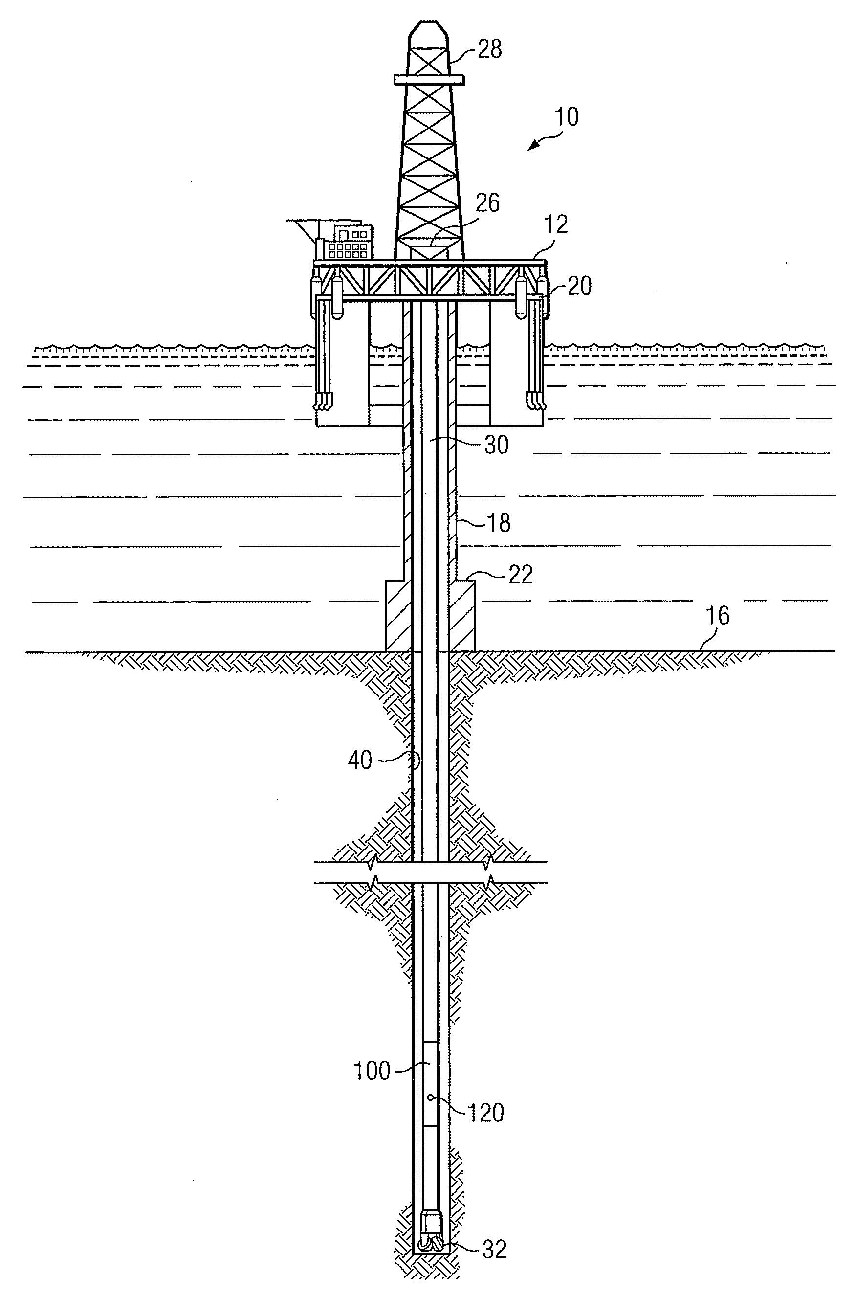
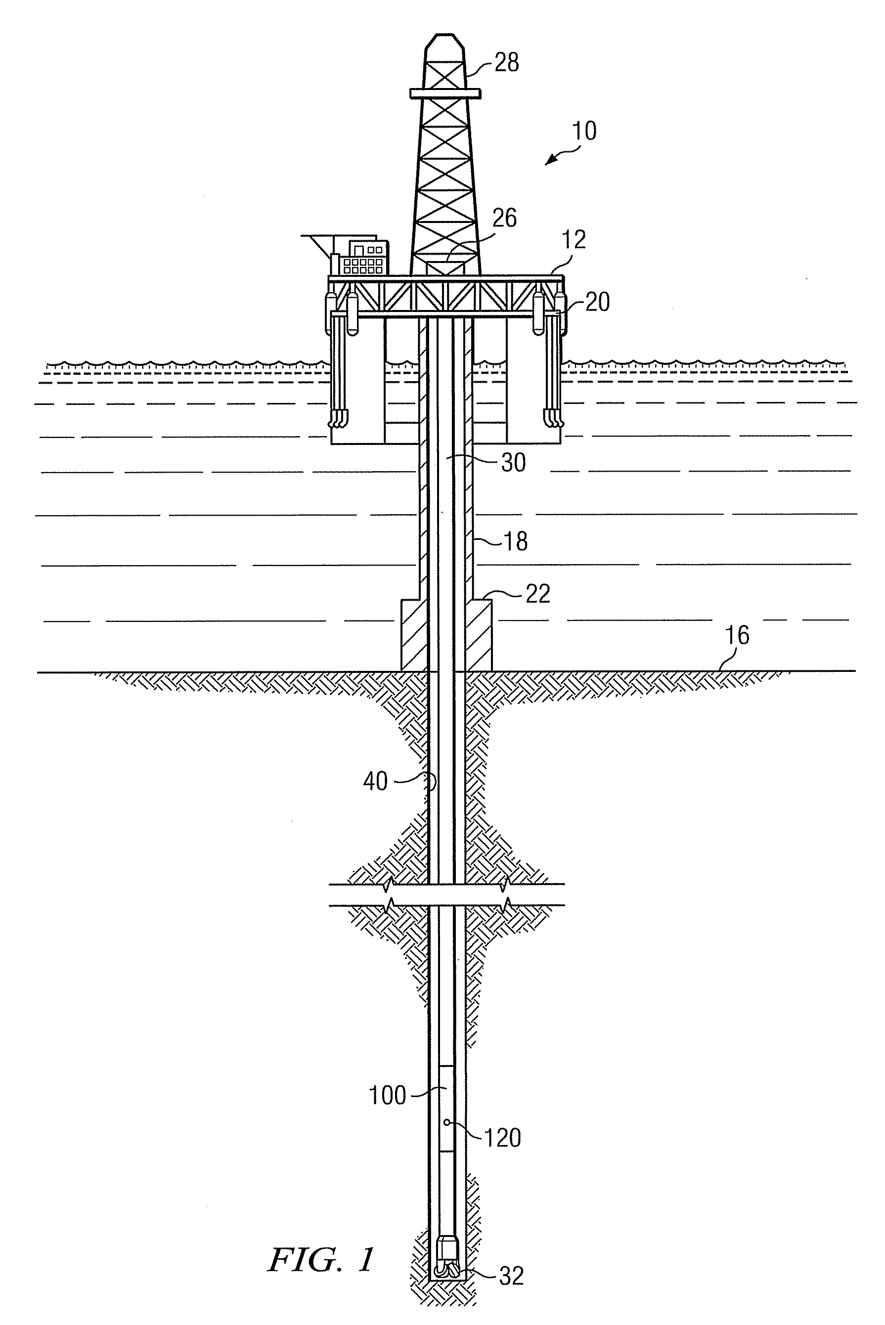
[0022]FIG. 1 depicts one exemplary embodiment of a logging while drilling tool 100 in accordance with the present invention in use in an offshore oil or gas drilling assembly, generally denoted 10. In FIG. 1, a semisubmersible drilling platform 12 is positioned over an oil or gas formation (not shown) disposed below the sea floor 16. A subsea conduit 18 extends from deck 20 of platform 12 to a wellhead installation 22. The platform m...


PUM


Abstract

A downhole tool includes circumferentially spaced and/or angled transducer elements. In one embodiment a standoff sensor has at least three piezoelectric transducer elements, at least a first element of which is configured to both transmit and receive ultrasonic energy. At least second and third of the elements are configured to receive ultrasonic energy transmitted by the first element in pitch catch mode. An electronic controller is configured to calculate a standoff distance from the ultrasonic waveforms received at the first, the second, and the third piezoelectric transducer elements. The controller may further be configured to estimate the eccentricity of a measurement tool in the borehole. Exemplary embodiments of the invention may improve borehole coverage and data quality and reliability in LWD caliper logging. In particular, the invention may advantageously reduce or even eliminate blind spots when logging eccentric bore holes.

Description

FIELD OF THE INVENTION[0001]The present invention relates generally to a downhole tool for making standoff and caliper measurements. More particularly, exemplary embodiments of the invention relate to a downhole tool having at least one angled ultrasonic transducer. Another exemplary embodiment of the invention relates to a standoff sensor including at least first, second, and third transducer elements.BACKGROUND OF THE INVENTION[0002]Logging while drilling (LWD) techniques are well-known in the downhole drilling industry and are commonly used to measure various formation properties during drilling. Such LWD techniques include, for example, natural gamma ray, spectral density, neutron density, inductive and galvanic resistivity, acoustic velocity, and the like. Many such LWD techniques require that the standoff distance between the various logging sensors in the drill string and the borehole wall be known with a reasonable degree of accuracy. For example, LWD nuclear / neutron measure...

Claims


Application Information

Patent Timeline
IPC IPC(8): E21B44/00
CPCE21B47/082E21B47/085
Inventor HAN, WEIWANG, TSILI
Owner SCHLUMBERGER TECH CORP
Why Eureka
Try Eureka