Thermal management system using micro heat pipe for thermal management of electronic components

a technology of electronic components and management systems, applied in metal-working equipment, semiconductor devices, lighting and heating equipment, etc., can solve the problem of limiting the enhancement of performance and heat removal

Inactive Publication Date: 2010-06-24
KAZAK COMPOSITES
View PDF3 Cites 20 Cited by
  • Summary
  • Abstract
  • Description
  • Claims
  • Application Information

AI Technical Summary

Problems solved by technology

As electronic components become more miniaturized and the number of interconnects per chip increases, heat removal becomes a limiting barrier to enhanced performance.

Method used


Image

  • Thermal management system using micro heat pipe for thermal management of electronic components
  • Thermal management system using micro heat pipe for thermal management of electronic components
  • Thermal management system using micro heat pipe for thermal management of electronic components

Examples


Embodiment Construction

[0014]The disclosure of U.S. Provisional Application No. 61 / 109,004, filed Oct. 28, 2008, is incorporated by reference herein.

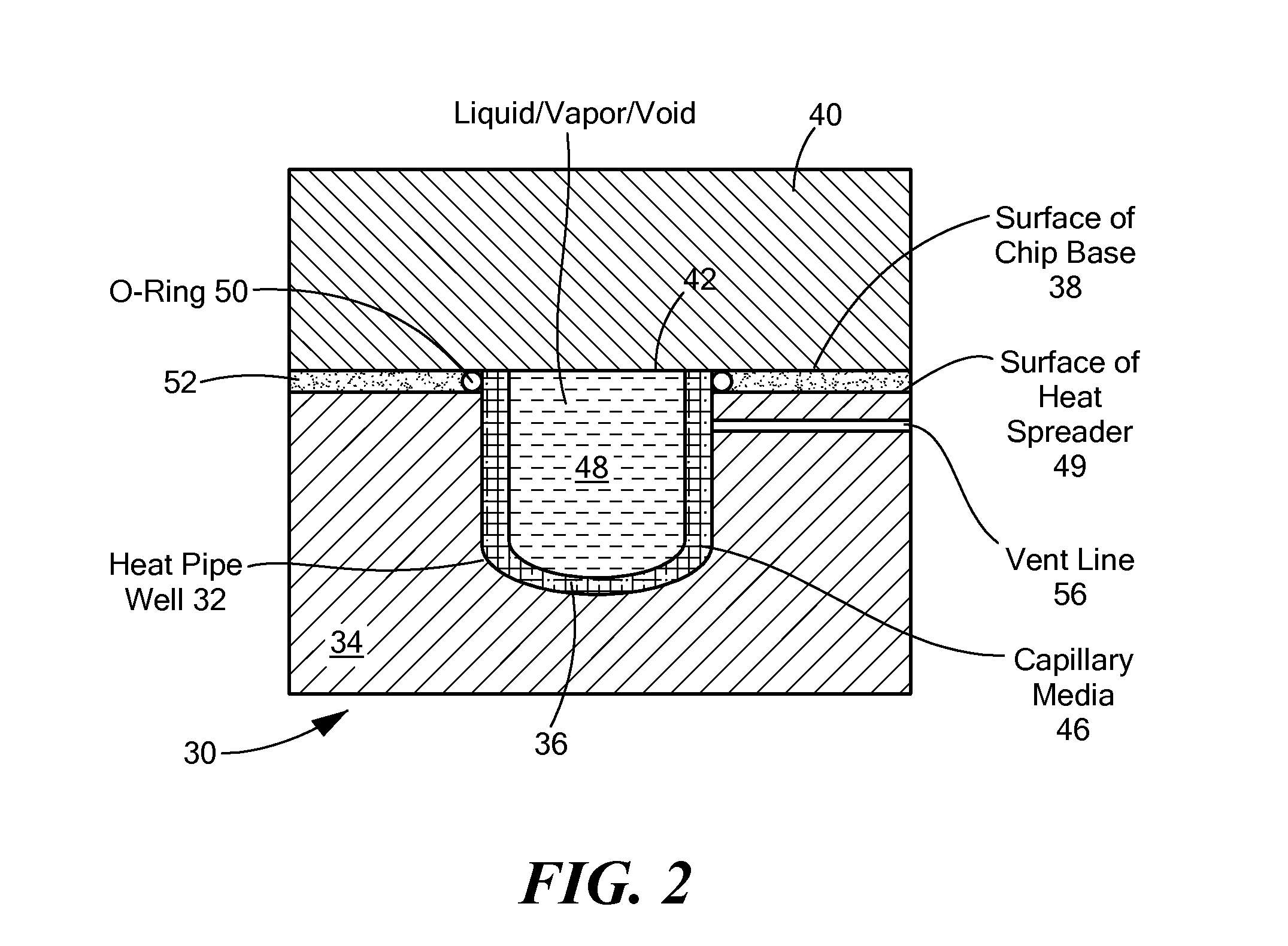
[0015]A bottleneck in transferring heat between components of electronics systems lies at the thermal interfaces between components. Depending on the specific components involved, this thermal interface may be between the die itself and a heat slug or spreader, or a heat slug and heat spreader, or a heat spreader and heat sink. In these cases, an imperfect but comparatively flat surface is presented to be brought into intimate contact with another corresponding flat surface. Except for the die itself, the surfaces are typically metallic, with copper, copper / molybdenum and aluminum being common.

[0016]None of these components has a completely smooth surface, and air pockets exist between the two materials. Air has a very high thermal resistance and hence is a poor heat conductor. To improve the thermal pathway at this interface, thermal compounds are used to fi...


PUM

PropertyMeasurementUnit
lengthsaaaaaaaaaa
lengthsaaaaaaaaaa
heat transferaaaaaaaaaa

Abstract

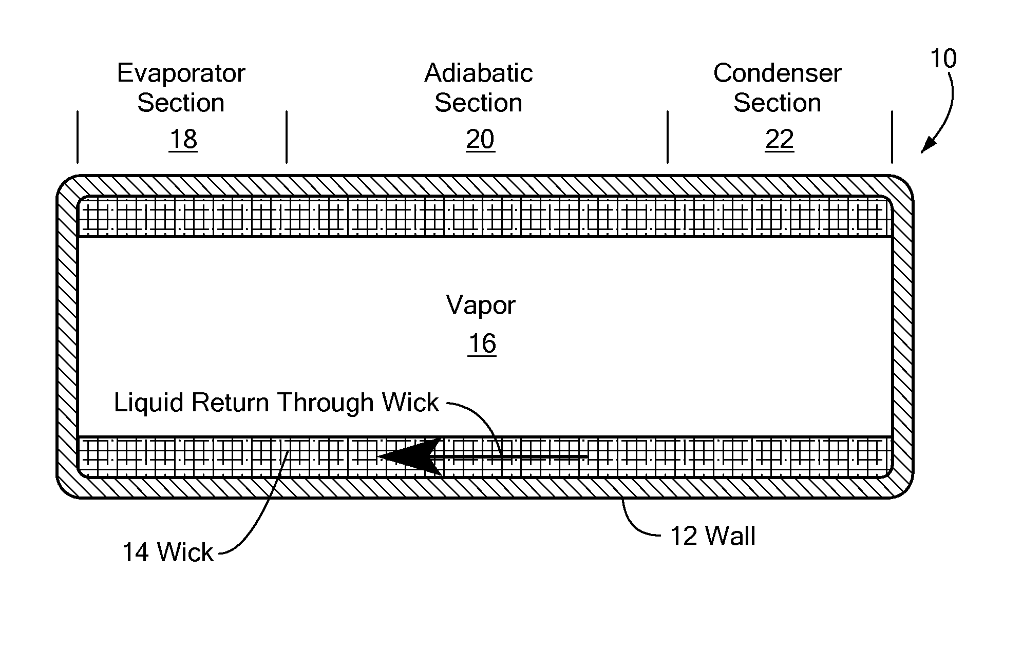
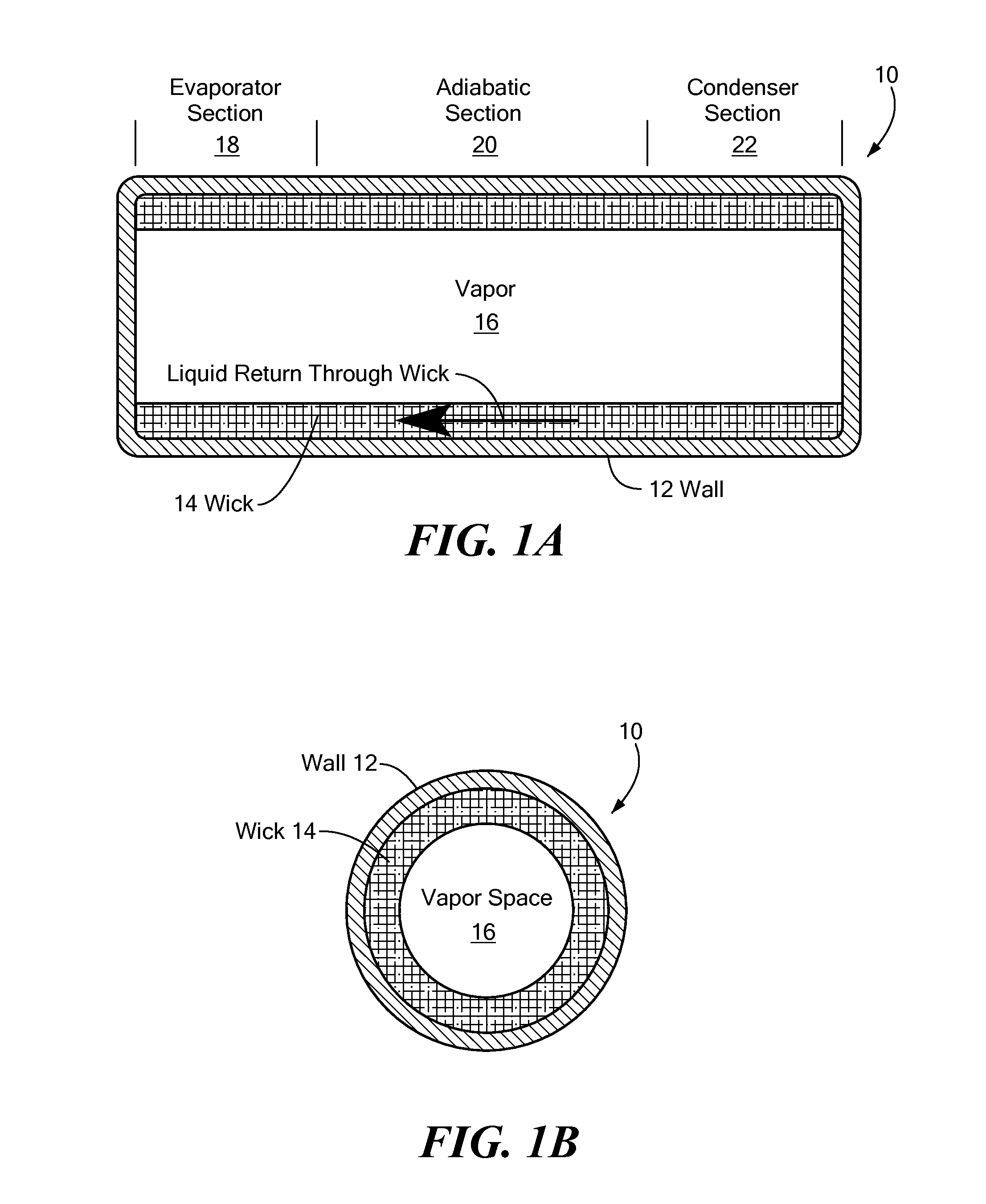
A thermal management system includes a base element and a heat producing element disposed for heat transfer from the heat producing element to the base element. An adherent zone includes an adherent element in physical attachment between the heat producing element and the base element. A heat transfer zone, separate from the adherent zone, includes a heat pipe between the heat producing element and the base element. The heat pipe includes a circulatory flow path between an evaporator section and a condenser section, and a working fluid on the circulatory flow path.

Description

CROSS REFERENCE TO RELATED APPLICATIONS[0001]Benefit is claimed under 35 U.S.C. §119(e) of U.S. Provisional Application No. 61 / 109,004, filed Oct. 28, 2008, the disclosure of which is incorporated by reference herein.STATEMENT REGARDING FEDERALLY SPONSORED RESEARCH OR DEVELOPMENT[0002]This invention was made under Air Force Contract FA8650-09-M-5013. The Government may have certain rights to this invention.BACKGROUND OF THE INVENTION[0003]As electronic components become more miniaturized and the number of interconnects per chip increases, heat removal becomes a limiting barrier to enhanced performance. A principal pathway for heat removal is via conductance from the chip base to a heat spreader and from the heat spreader to the printed wire board or possibly to a heat sink device. Adherent substances, commonly epoxy resins, filled with thermally conductive particulates such as carbon or aluminum are used as an attachment layer between the electronic components.[0004]An evaporative c...

Claims


Application Information

Patent Timeline
Patent Type & Authority Applications(United States)
IPC IPC(8): F28D15/02B21D53/02
CPCF28D15/046H01L23/427H01L2924/09701Y10T29/4935H01L2924/0002F28D2015/0225H01L2924/00
Inventor HOLLEY, WOODROW W.FANUCCI, JEROME P.
Owner KAZAK COMPOSITES
Why Eureka
Try Eureka