Power tool

a technology of power tools and dust collection, which is applied in the field of dust collection techniques of power tools, can solve problems such as the inability to operate the power tools, and achieve the effects of reducing the amount of dust entering the carbon brush, reducing the cost of repair, and facilitating the replacement of the tool bi

Active Publication Date: 2010-06-24
MAKITA CORP
View PDF14 Cites 29 Cited by
  • Summary
  • Abstract
  • Description
  • Claims
  • Application Information

AI Technical Summary

Benefits of technology

[0016]According to a further aspect of the invention, replacement of the tool bit can be made with the dust suction part mounted to the tip end region of tool body. With such a construction, for each replacement of the tool bit, it is not necessary to take the trouble of detaching the dust suction part from the tool body. Therefore, replacement of the tool bit can be efficiently performed.
[0017]According to a further aspect of the invention, the dust suction part may include a movable region that can expand and contract and is formed by a tubular bellows in a region which covers the tool bit, and a fixed region which is mounted to the tip end region of the tool body. Further, the movable region is removable from the fixed region so that replacement of the movable region can be made. According to this aspect, replacement of only the movable region which is formed by the bellows and susceptible to damage because of being movable, or partial replacement can be allowed. Such a construction is effective in reducing the cost of repair.
[0018]According to a further aspect of the invention, openings may be formed in the dust transfer passage and may provide a communication between the dust transfer passage and an internal space of the tool body. According to this aspect, when the dust collector is driven, dust generated during operation is sucked by the dust suction part, then led through the dust transfer passage and discharged out into the dust collecting hose through the dust discharge port. In this case, air flow into the dust transfer passage through the openings is generated within the internal space of the tool body. Therefore, heat within the internal space of the tool body can be allowed to escape to the outside through the dust transfer passage, so that the tool body can be cooled. Further, in a power tool, dust generated during operation may enter a tool body, stick to a carbon brush of the motor and exert an adverse effect on the sliding movement of the carbon brush on a commutator. Therefore, according to this embodiment, dust which enters the internal space is sucked together with air into the dust transfer passage through the openings. Thus, the amount of entry of dust toward the carbon brush can be reduced, so that the carbon brush can be protected against the adverse effect of dust.

Problems solved by technology

In such a power tool, however, provision of the dust suction device may impair operability of the power tool when a user holds a handle and performs an operation.

Method used


Image

  • Power tool
  • Power tool
  • Power tool

Examples


first representative embodiment

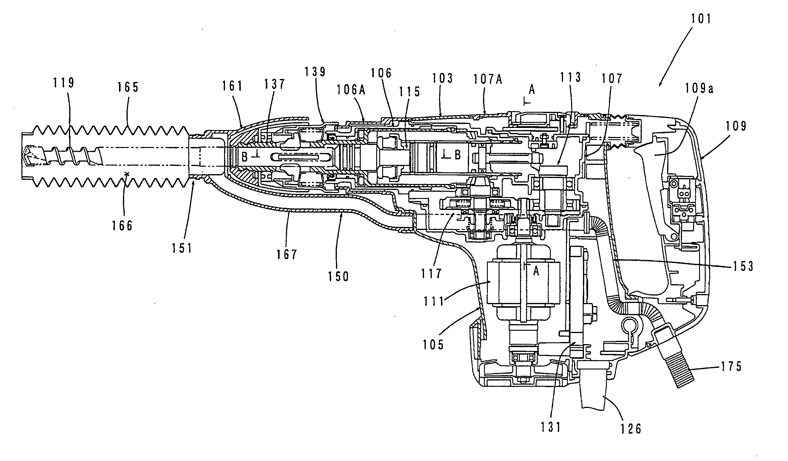
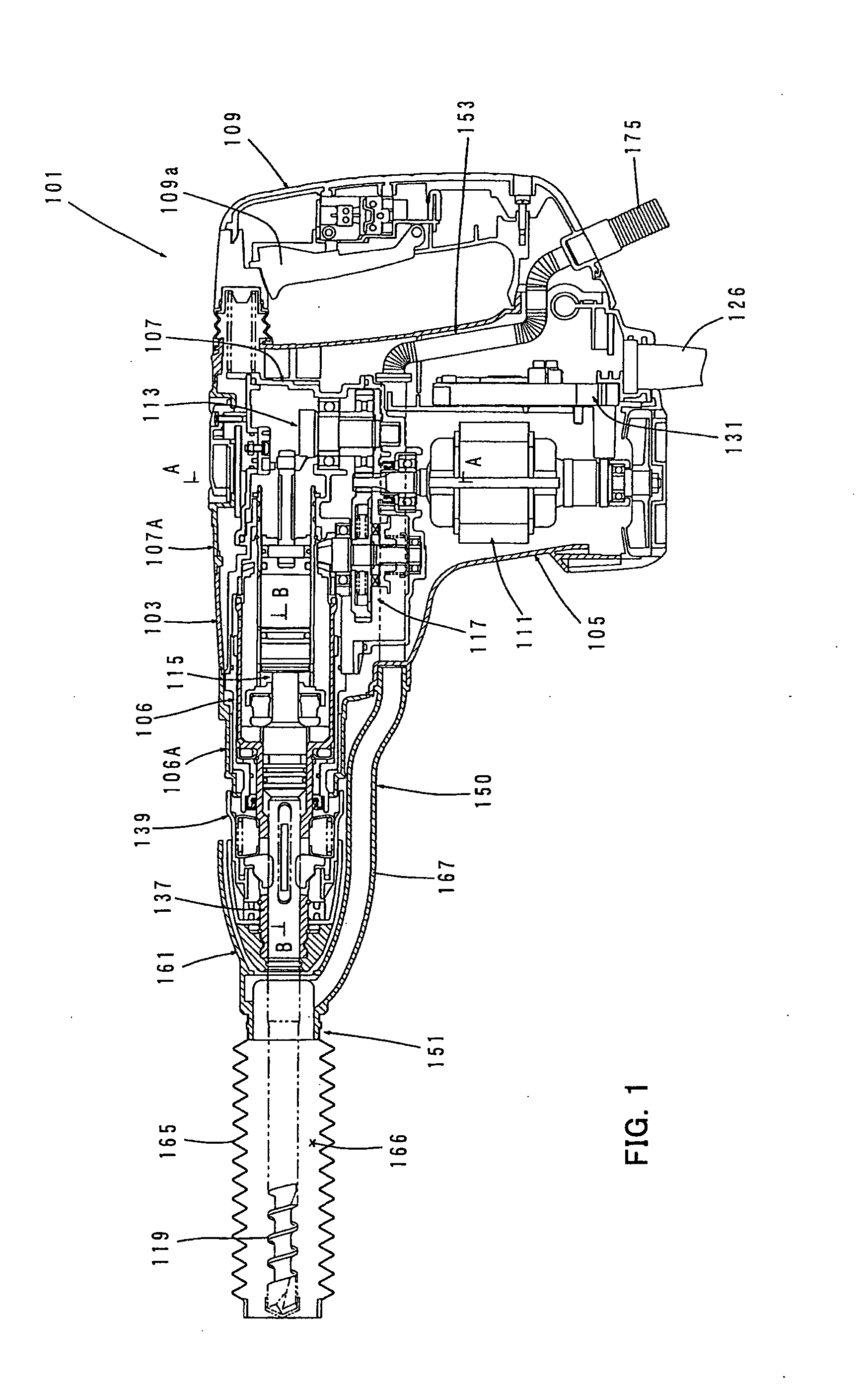
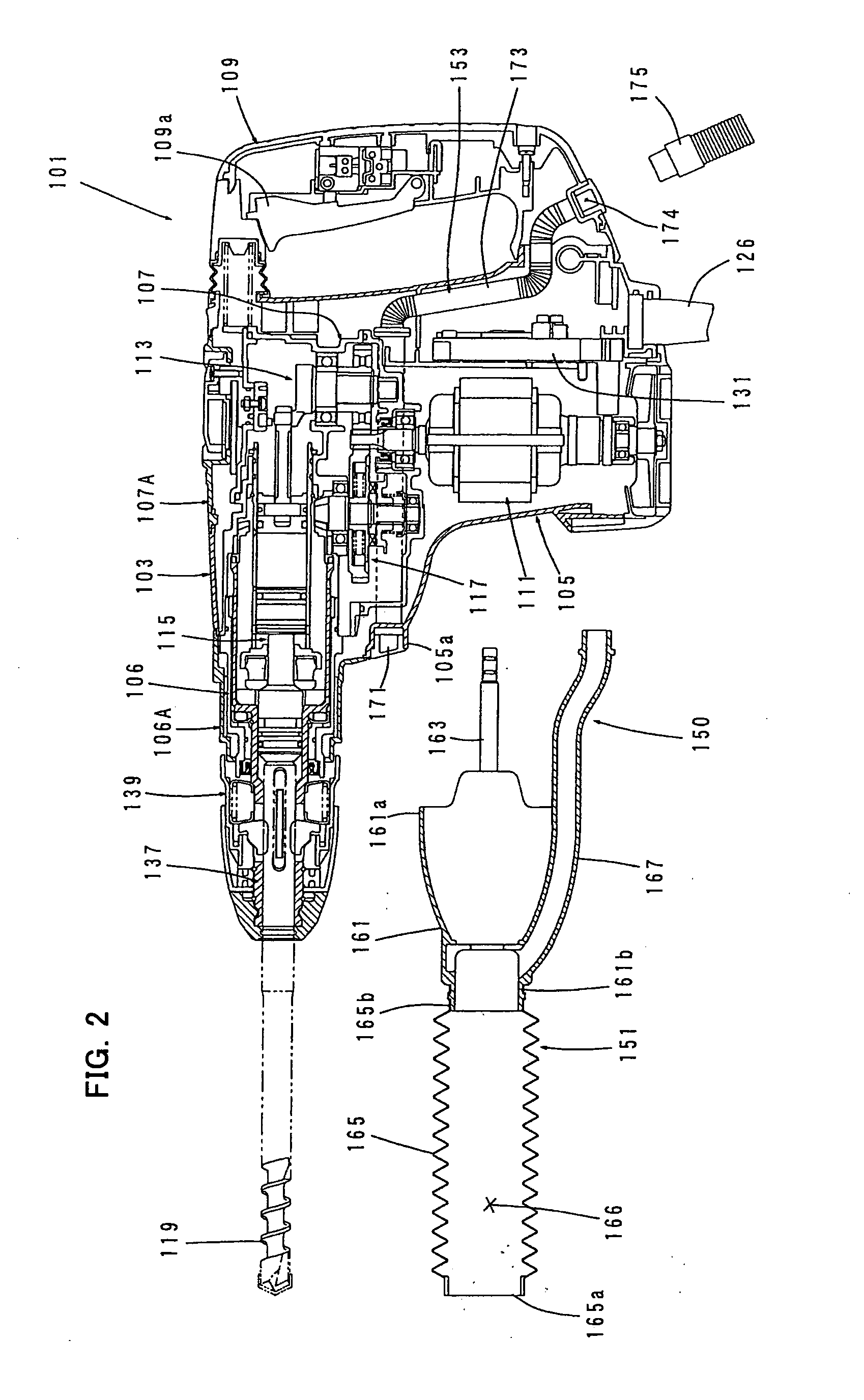
[0043]A first representative embodiment of the invention is now described with reference to FIGS. 1 to 6. In the first embodiment, an electric hammer drill is explained as a representative example of a power tool according to the invention. FIGS. 1 and 2 mainly show an entire electric hammer drill 101. FIG. 2 shows the state in which a dust suction unit 151 is not yet attached to the hammer drill 101. FIGS. 3 and 4 are partially enlarged sectional views of FIG. 1. FIG. 5 is a sectional view taken along line A-A in FIG. 1 and FIG. 6 is a sectional view taken along line B-B in FIG. 1.

[0044]As shown in FIGS. 1 to 4, the representative hammer drill 101 includes a body 103 that forms an outer shell of the hammer drill 101, a hammer bit 119 detachably coupled to a tip end region (left end as viewed in FIG. 1) of the body 103 via a tool holder 137, and a handgrip 109 designed to be held by a user and connected to the body 103 on the side opposite to the hammer bit 119. The body 103, the ha...

second representative embodiment

[0070]A second representative embodiment of the invention is now described with reference to FIGS. 7 to 10. In the second embodiment, in addition to the handgrip 109, a side grip 181 is mounted to the body 103 of the hammer drill 101. In the other points, it has the same construction as the above-described first embodiment. Therefore, components and elements which are substantially identical to those in the first embodiment are given like numerals and are not described or only briefly described. The side grip 181 is a feature that corresponds to the “side handle” according to this invention.

[0071]The side grip 144 is a rod-like member that extends horizontally in a direction transverse to the axial direction of the hammer bit 119 and mainly includes a grip body 182 that is detachably mounted to the barrel cover 106A and a grip part 183 to be held by a user. The grip part 183 is formed by a hollow cylindrical member connected at one longitudinal end to the grip body 182. A grip mount...

third representative embodiment

[0077]A third representative embodiment of the invention is now described with reference to FIGS. 11 to 19. In this embodiment, as shown in FIGS. 11 to 15, a plurality of suction holes 172 are formed in the dust transfer passage 153 disposed within the body 103 in the hammer drill 101 and serve to provide communication between the inside of the dust transfer passage 153 and the space S of the body 103 (space between the inner housing and the outer housing) such that heat within the body 103 and dust which enters the body 103 are allowed to escape to the outside through the suction holes 172.

[0078]Specifically, in the pipe 171 which is disposed in the space S formed between the inner wall surface of the motor housing 105 and the outer wall surface of the lower region of the gear housing 107 covered by the motor housing 105, the suction holes 172 are formed to provide communication between the inside of the pipe 171 and the space S, so that heat generated within the body 103 and dust ...


PUM

PropertyMeasurementUnit
poweraaaaaaaaaa
flexibleaaaaaaaaaa
shapeaaaaaaaaaa

Abstract

It is an object of the invention to provide an effective technique for reducing adverse effect of a dust suction device on the operability of a power tool, in the power tool which can suck dust generated during operation. The power tool has a motor 111 and a tool body 103 that houses the motor 111. A tool bit 119 is coupled to a tip end region of the tool body and driven by the motor 111 to perform a predetermined operation. The power tool further includes a dust suction part 151 through which dust generated during operation by the tool bit 119 is sucked and which covers at least a tip end of the tool bit 119, a dust transfer passage 153 through which the dust sucked into the dust suction part 151 is transferred and which is partly disposed within the tool body 103, and a dust discharge port 174 through which the dust transferred through the dust transfer passage 153 is discharged to the outside. Further, the dust discharge port 174 is disposed on the opposite side of the motor 111 from the tool bit 119.

Description

BACKGROUND OF THE INVENTION[0001]1. Field of the Invention[0002]The invention relates to a dust collecting technique for power tools.[0003]2. Description of the Related Art[0004]Japanese laid-open patent publication No. 10-217065 discloses power tool with a dust suction device in which a suction path is provided by forming a hollow tool bit. Dust generated during operation is sucked by a suction fan from the suction path into a suction chamber through a suction passage formed within the tool body and then, collected in a collecting container connected to the suction chamber.[0005]In such a power tool, however, provision of the dust suction device may impair operability of the power tool when a user holds a handle and performs an operation.SUMMARY OF THE INVENTION[0006]Accordingly, it is an object of the invention to provide a more effective dust collection in a power tool.[0007]Above described object can be achieved by the claimed invention. According to an aspect of the invention, ...

Claims


Application Information

Patent Timeline
Patent Type & Authority Applications(United States)
IPC IPC(8): B25D17/18B23B47/34
CPCB23Q11/0046Y10T408/44Y10T408/564B25F3/00B25F5/026
Inventor FURUSAWA, MASANORIKASUYA, YOSHIHIROTAKEUCHI, HAJIME
Owner MAKITA CORP
Why Eureka
Try Eureka