[0005]The disclosed
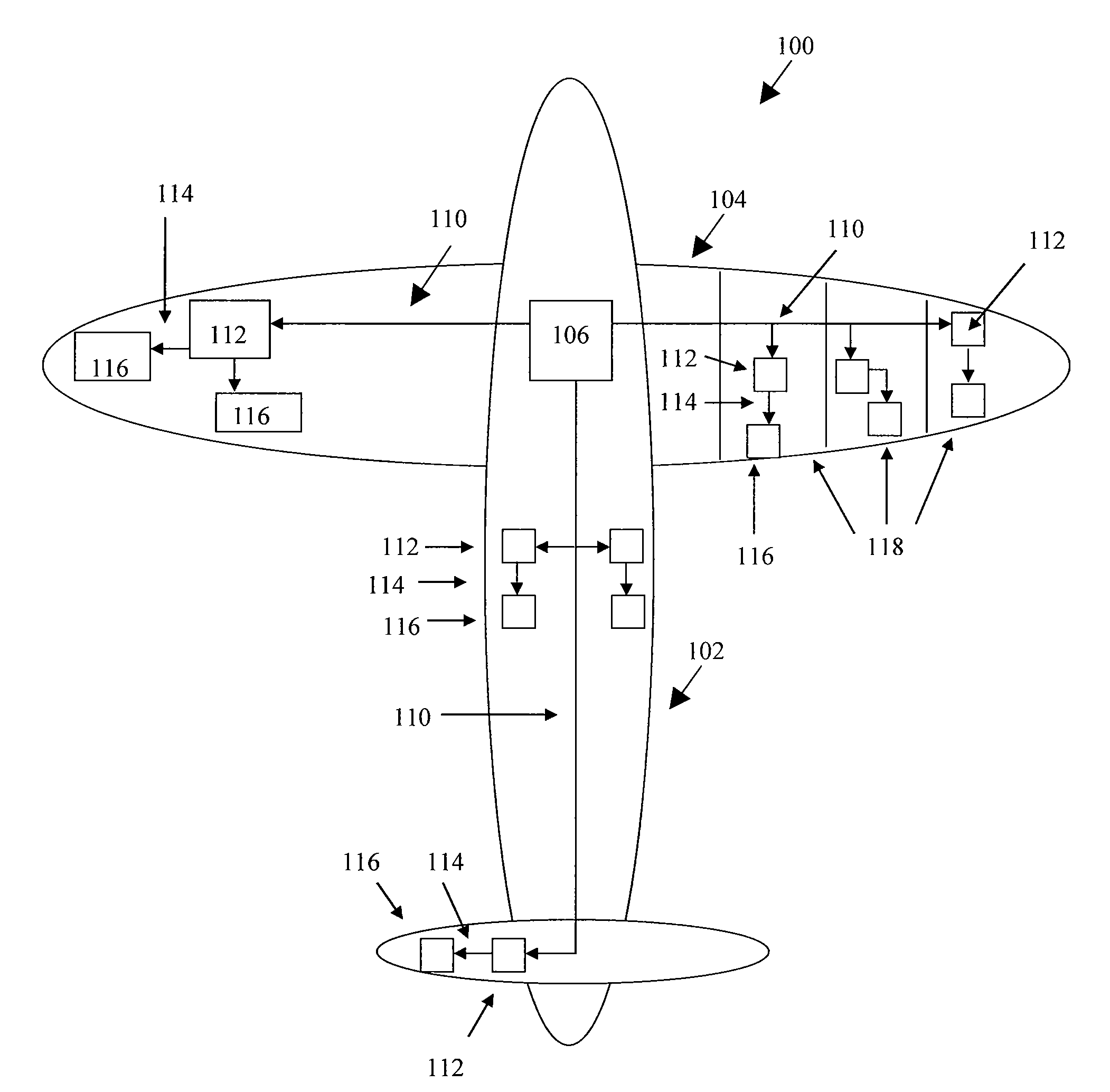
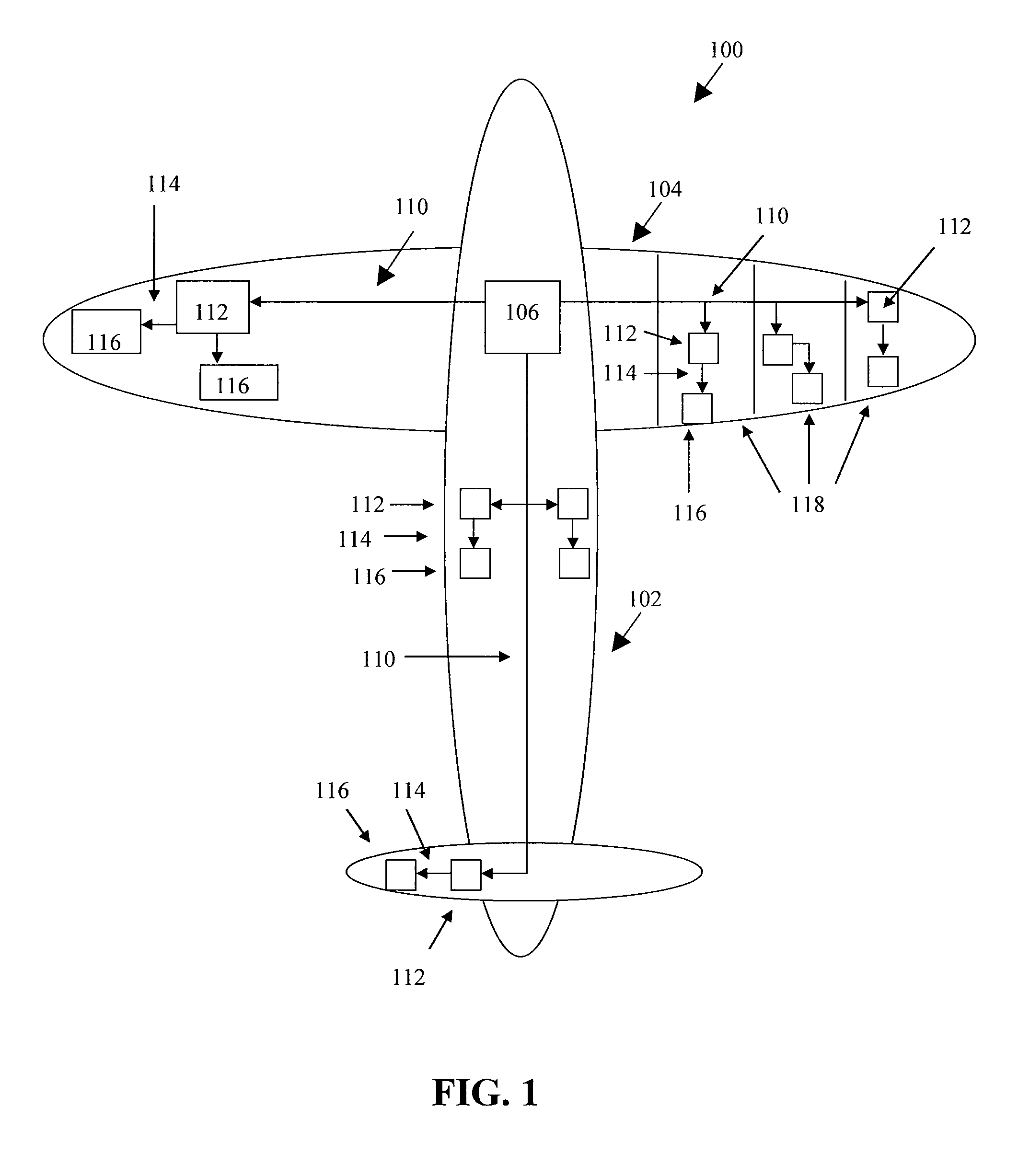
system and method may enhance endurance, maneuverability, operational capability, and / or maximum sustainable altitude of an aircraft. An actuator interface controller may be provided that interfaces with a remote device located throughout the aircraft, such as in the wings, the
tail,
landing gear, the
fuselage, and other locations. The interface controller may accept a high
voltage from a high
voltage power bus, and then provide a stepped down or lower voltage to a
low voltage power bus to power the remote device. The interface controller may
relay commands received from a
control network that direct the operation of the remote device. The interface controller may provide
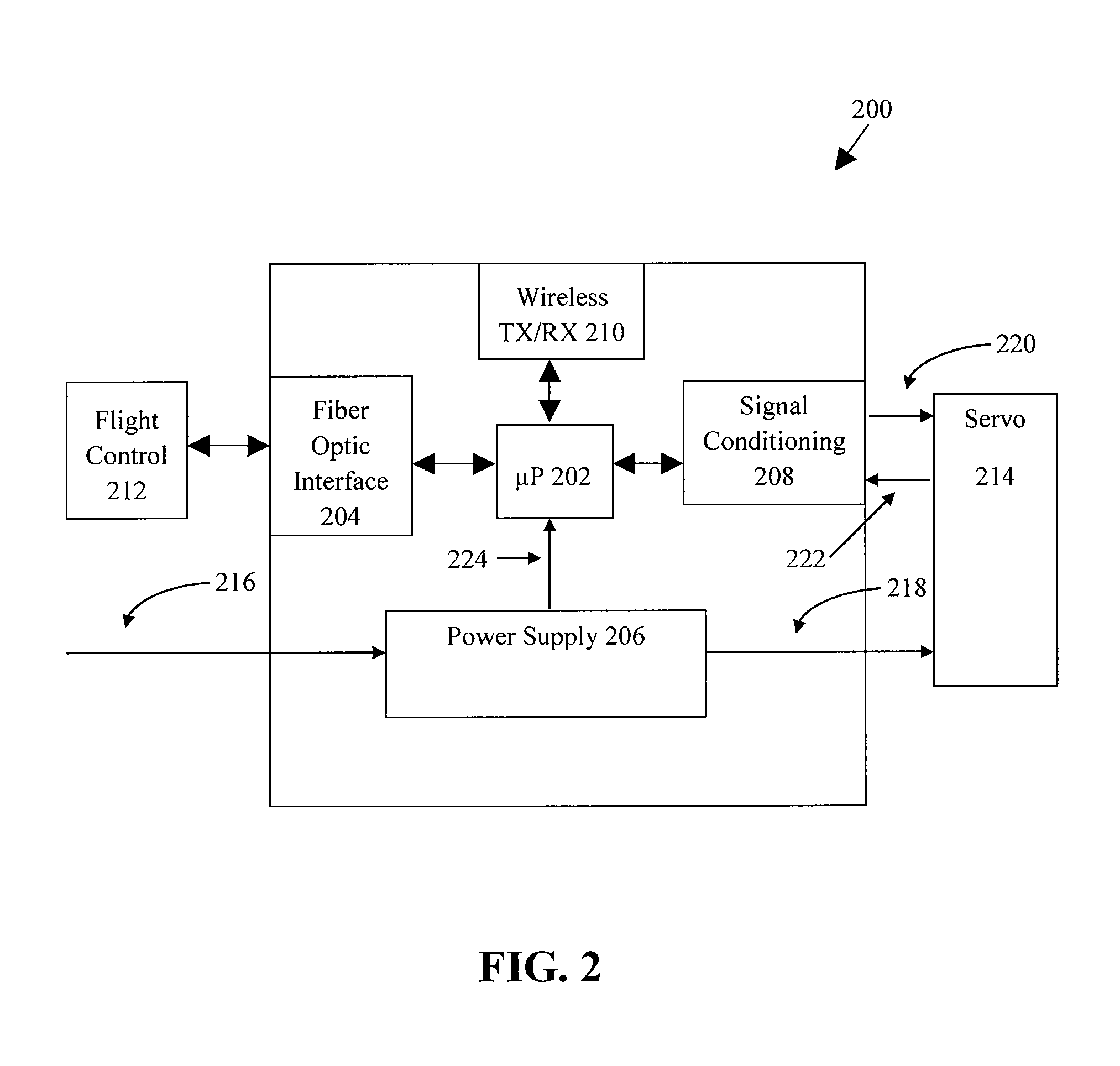
signal conditioning for (a) command signals sent from a local processor located on the interface controller to the remote device, and (b) feedback signals received from the remote device. The interface controller may communicate the feedback related to the operation of the remote device to the control network.
[0006]In one embodiment, a
system for supplying power to a remote auxiliary load located in an aircraft may be provided. The
system may include an actuator interface controller located in the aircraft comprising a power supply. The power supply may be interconnected with a high gage wire and a low gage wire, with the high gage wire being of higher gage wiring than the low gage wire. The high gage wire may act as a high voltage power bus and provide a high voltage input to the power supply. The power supply may be configured to step down the high voltage received to a
low voltage that is lower than the high voltage on the high voltage power bus and place the
low voltage onto the low gage wire that may act as a low voltage power bus. The low voltage power bus may be interconnected with the remote auxiliary load and provide the low voltage to the remote auxiliary load. The remote auxiliary load may be located at a distance from a power
plant of the aircraft. As a result, both a length of low gage wiring acting as a low voltage power bus and a longer length of relatively lighter high gage wire acting as a high voltage power bus may be used to
relay power from the power
plant of the aircraft to the remote auxiliary load, reducing an overall weight of wiring located in the aircraft required to supply power to the remote auxiliary load.
[0007]In another embodiment, a system for supplying power to a remote device located in an aircraft may be provided. The system may include an actuator interface controller interconnected with a high voltage power bus and having a power supply. The power supply may be configured to reduce a high voltage received from the high voltage power bus to a low voltage of a low voltage power bus and to place the low voltage onto the low voltage power bus exiting the actuator interface controller. The high voltage power bus have a first thickness and a first weight per
unit distance. The low voltage power bus may have a second thickness and a second weight per
unit distance. The low voltage of the low voltage power bus may be less than the high voltage of the high voltage power bus. The second thickness and the second weight per
unit distance of the low voltage power bus may be greater than the first thickness and the first weight per unit distance of the high voltage power bus such that the high voltage power bus is comparatively lighter than the low voltage power bus per unit distance. The system may include a remote device interconnected with the low voltage power bus and that is powered from the low voltage carried by the low voltage power bus. As a result, power may be transmitted to the remote device over both the low voltage power bus and the relatively lighter high voltage power bus, reducing an overall weight of wiring in the aircraft required to supply power to the remote device.
[0008]In another embodiment, a method of controlling and supplying power to a remote device located in an aircraft may be provided. The method may include providing an interface controller located at a first position in the aircraft, and interconnecting a high gage wire with the interface controller. The high gage wire may run from a power
plant located in the
fuselage of the aircraft to the interface controller located at the first position for a first distance. The method may include interconnecting a comparatively lower low gage wire with respect to the high gage wire to the interface controller. The low gage wire may run from the interface controller to the remote device located at a second position in the aircraft for a second distance. The high gage wire may have less weight per unit distance and thickness than the lower gage wire. The method may include placing a high voltage generated from the power plant located in the
fuselage onto the high gage wire running to the interface controller, and stepping down the high voltage via a
voltage converter associated with the interface controller to a low voltage that is lower than the high voltage and placing the low voltage onto the low gage wire to power the remote device. As a result, the remote device located in the aircraft is
transmitted power from the power plant located in the fuselage over both low gage wire and relatively lighter high gage wire thereby reducing an overall weight of the wiring in the aircraft required to power the remote device.

