Microwave filter based on a novel combination of single-mode and dual-mode cavities

Active Publication Date: 2010-06-24
GEMTEK TECH CO LTD
View PDF1 Cites 0 Cited by
  • Summary
  • Abstract
  • Description
  • Claims
  • Application Information

AI Technical Summary

Benefits of technology

[0008]The single-mode cavity extends from the dual-mode cavity with respect to the symmetric reference plane. The single-mode cavity is physically symmetric to the symmetric plane. The single-mode cavity connects the dual-mode cavity with a connecting passage which can effectively control the coupling strength between cavities.
[0011]In conclusion, the microwave filter of the present invention is physically symmetric. That is only half of physical dimension of the microwave filter need to be designed for a prescribed response, which makes the microwave filter easier to design and manufacture when compared to the prior art in FIG. 1. Concerning with electrical performance, the proposed microwave filter is in extended-doublet configuration and can generate a pair of finite transmission zeros on the upper and lower stopband, which makes it different from the prior art where two dual-mode cavities are needed to generate and control two finite transmission zeros.

Problems solved by technology

The disadvantage of the all-inductive filters in documents 1 and 2 is that lots of physical parameters need to be carefully designed and adjusted since coupling topologies of filters are really complex (“Rosenberg, U. Amari, S., “Novel design possibilities for dual-mode filters without intracavity couplings”, Microwave and Wireless Components Letters, August 2002, pp.

Method used


Image

  • Microwave filter based on a novel combination of single-mode and dual-mode cavities
  • Microwave filter based on a novel combination of single-mode and dual-mode cavities
  • Microwave filter based on a novel combination of single-mode and dual-mode cavities

Examples


Embodiment Construction

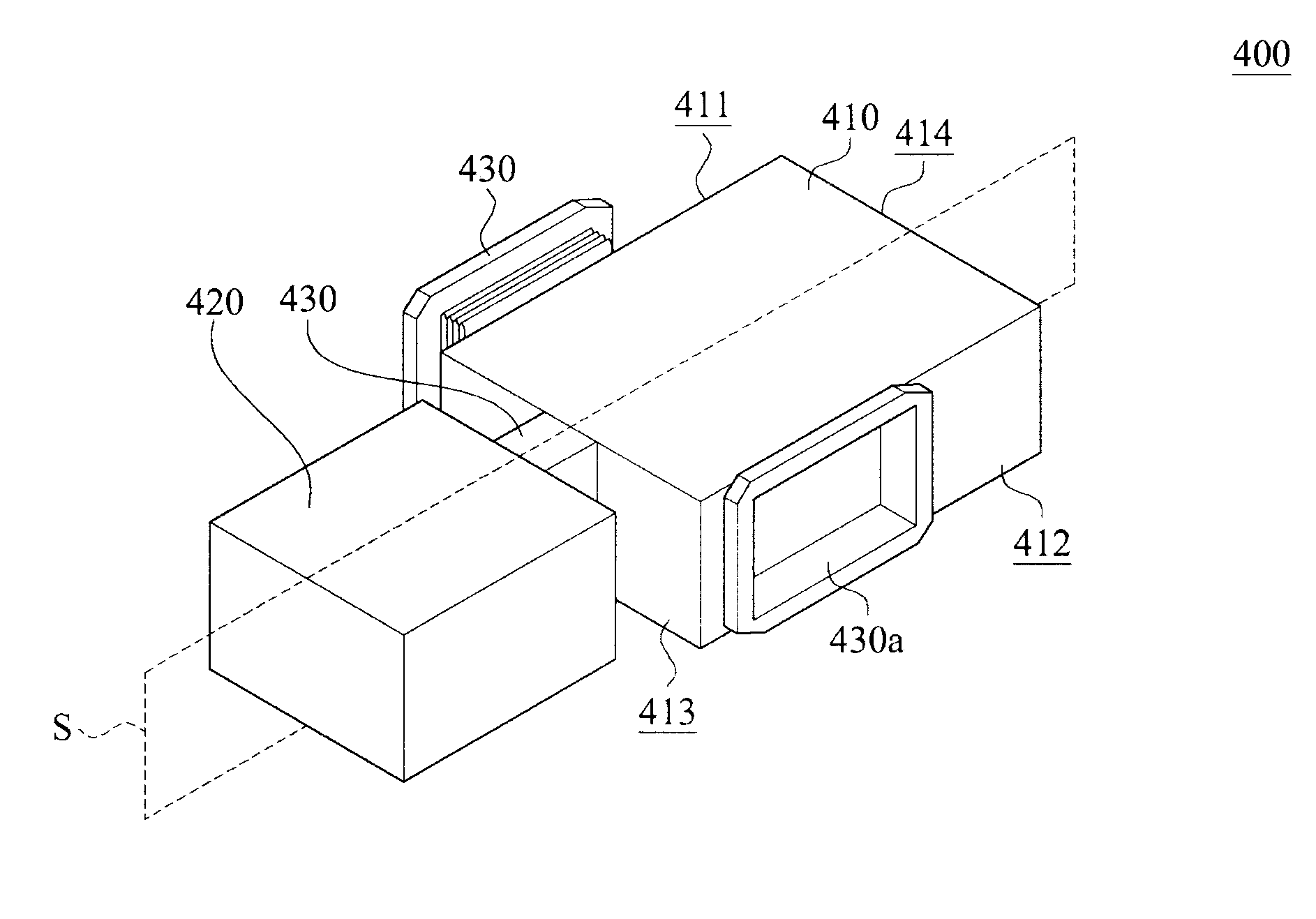
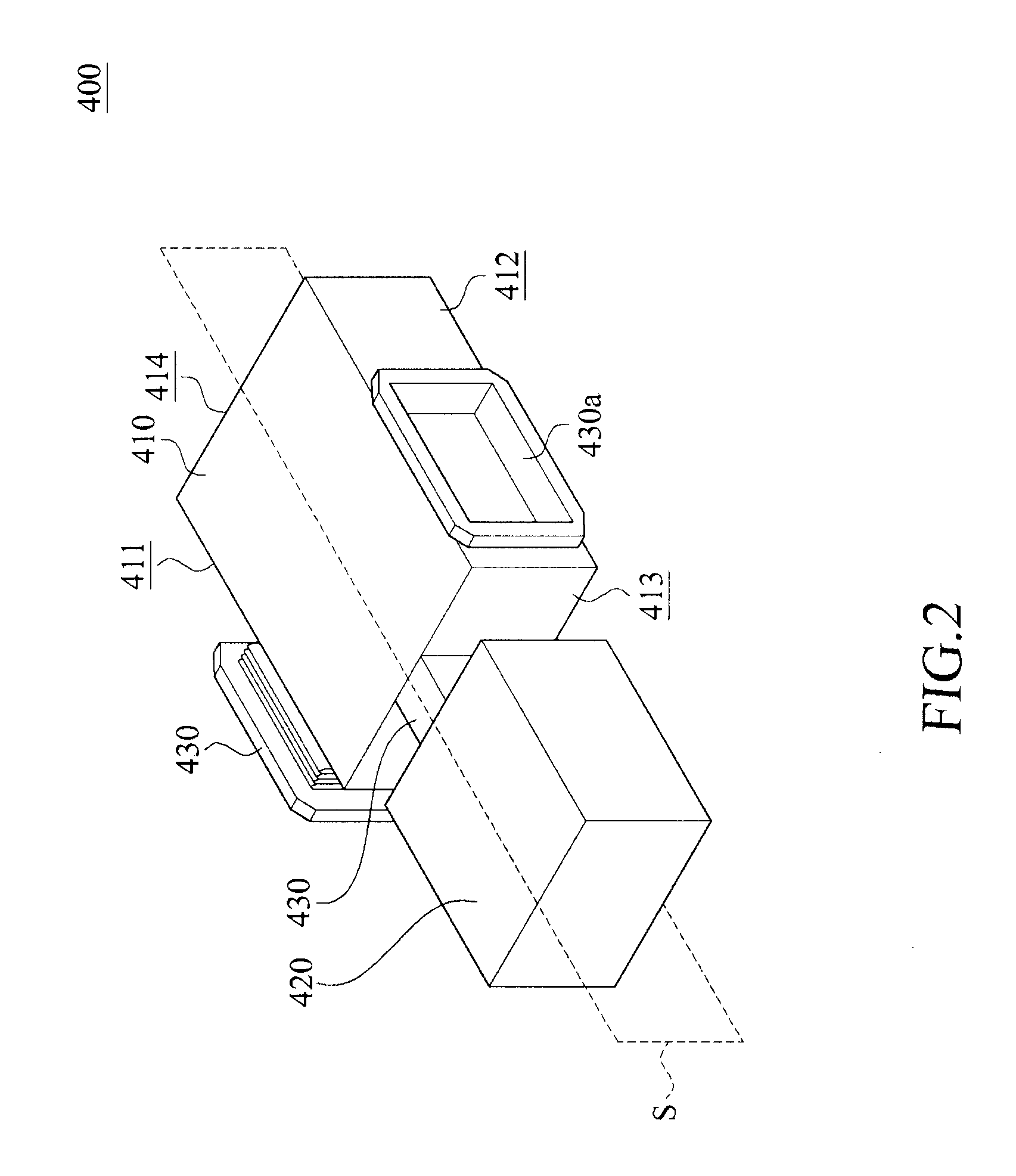
[0022]Please refer to FIG. 2, which is a perspective view illustrating the basic physical configuration of a microwave filter 400 according to a first embodiment of the present invention. FIG. 3 illustrates the microwave filter 400 coupling to an input waveguide 300 and an output waveguide 500.

[0023]The microwave filter 400 based on single-mode and dual-mode cavities is used for filtering an electromagnetic wave transmitted from the input waveguide 300 to the output waveguide 500. The microwave filter 400 can be a band-pass filter, so that the microwave filter 400 allows certain frequencies of the electromagnetic wave to be transmitted to the output waveguide 500 while rejecting the remaining frequencies.

[0024]The microwave filter 400 comprises a dual-mode cavity 410, a single-mode cavity 420, and a plurality of binding passages 430, 430a.

[0025]The dual-mode cavity 410 has a rectangular shape and is symmetric to a symmetric reference plane S. The dual-mode cavity 410 has a first si...


PUM


Abstract

A microwave filter based on the combination of dual-mode and single-mode cavities. The single-mode cavity symmetrically extends from the dual-mode cavity with respect to the symmetric reference plane to form the so called extended doublet network. The microwave filter in extended-doublet configuration exhibit high frequency selectivity since it has a pair of finite frequency transmission zeros on the upper and lower stopband. The design concept can also be applied to build higher order filters.

Description

FIELD OF THE INVENTION[0001]The present invention is related to a microwave filter, and more particular to a microwave filter based on single-mode and dual-mode cavities.BACKGROUND OF THE INVENTION[0002]Please refer to document 1 (Patent U.S. Pat. No. 6,538,535 B2) and document 2 (Marco Guglielmi, Pierre Jarry, Eric Kerherve, Oliver Roquebrun, and Dietmar Schmitt, “A new family of all-inductive dual-mode filters”, IEEE trans. On Microwave theory & Tech., vol. 10, October 2001, pp. 1764-1769), the prior art provides a dual-mode waveguide filter 100 as shown in FIG. 1.[0003]The dual-mode waveguide filter 100 has two dual-mode cavities 110, 120 coupled to each other. The dual-mode cavities 110 has an opening 111 for coupling with an input waveguide (not shown), and the dual-mode cavities 120 has an opening 121 for coupling with an output waveguide (not shown).[0004]Instead of using circular or elliptical waveguide which is difficult to manufacture, the dual-mode waveguide filter 100 is...

Claims


Application Information

Patent Timeline
IPC IPC(8): H01P1/208
CPCH01P1/2082H01P1/208
Inventor LIAO, CHING-KU
Owner GEMTEK TECH CO LTD
Why Eureka
Try Eureka