Sensor and an imaging system for remotely detecting an object

a technology of an imaging system and an object, applied in the field of sensors and imaging systems for remotely detecting objects, can solve the problems of poor lateral resolution of radars, poor accuracy of both types of sensors, and high cos

Inactive Publication Date: 2010-06-24
LETAT FR REPRESENTE PAR LE LABE CENT DES PONTS & CHAUSEES
View PDF5 Cites 7 Cited by
  • Summary
  • Abstract
  • Description
  • Claims
  • Application Information

AI Technical Summary

Benefits of technology

[0056]Two main embodiments may be envisaged for varying the path length traveled by the reference beam relative to the total optical path length traveled by the incident beam and the reflected beam, and thus for varying the depth of the field of the imaging system:
[0057]In an embodiment, the system for varying the relative optical path length is a system for causing the sensor to move relative to the measured object. The measurement is then performed either by causing the imaging system to approach the measured object progressively, or by moving progressively away therefrom,...

Problems solved by technology

Firstly, at a large scale, it is known to make use of theodolites for measuring the relative positions of objects.
Radars enable the relative positions of reflecting targets to be measured under unfavorable weather conditions with good accuracy, but at high cost.
Nevertheless, neither of those two types of sensor is entirely satisfactory:
radars present poor lateral resolution, with angular fields of view that are very narrow, a few degrees only, thus making them unsuitable for detecting vehicles traveling on wide roads or on winding roads.
Furthermore, radars are poor or useless at detecting stationary obstacles situated beside the road or even on it.
Finally, when faced with an environment that is compl...

Method used


Image

  • Sensor and an imaging system for remotely detecting an object
  • Sensor and an imaging system for remotely detecting an object
  • Sensor and an imaging system for remotely detecting an object

Examples


Embodiment Construction

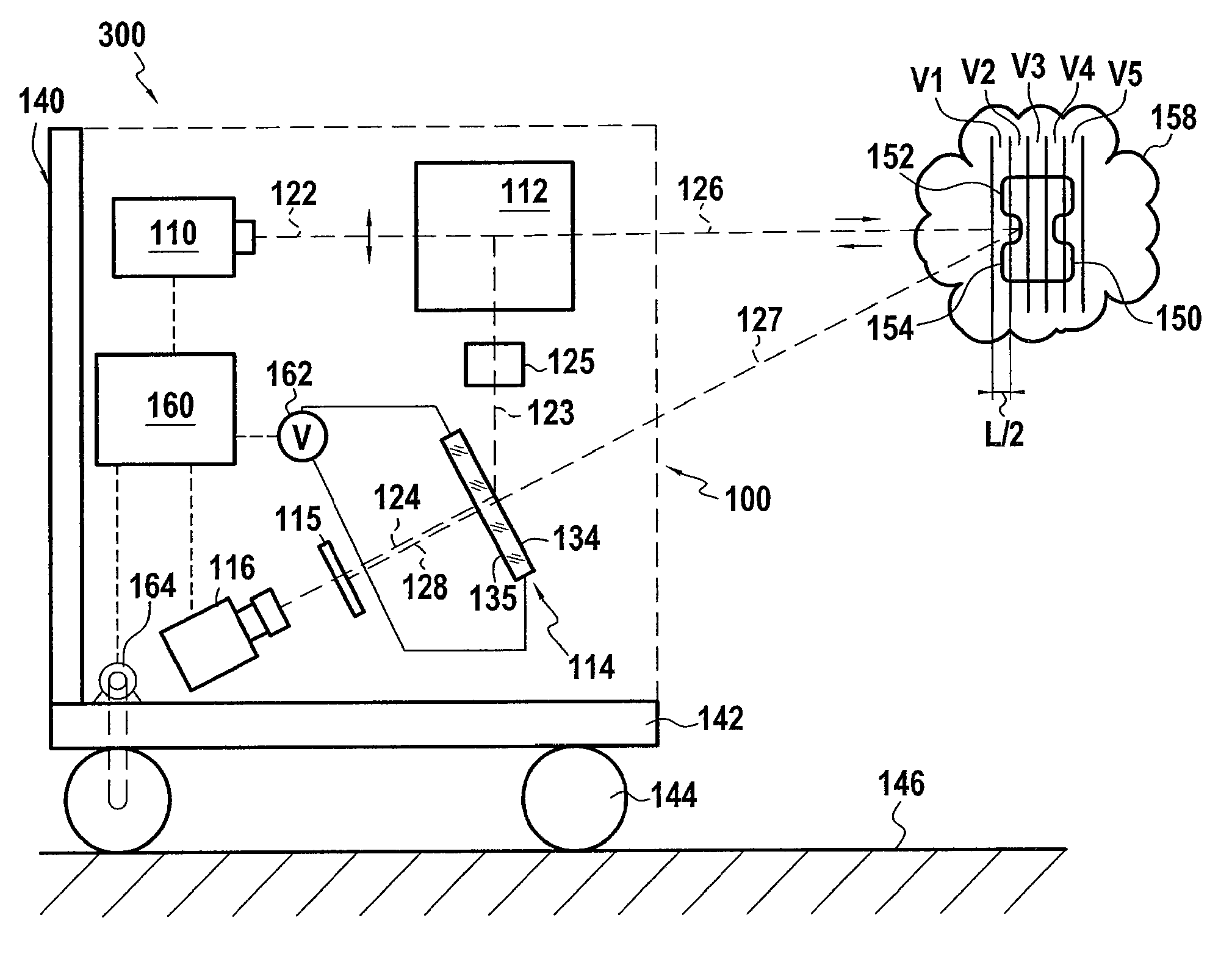
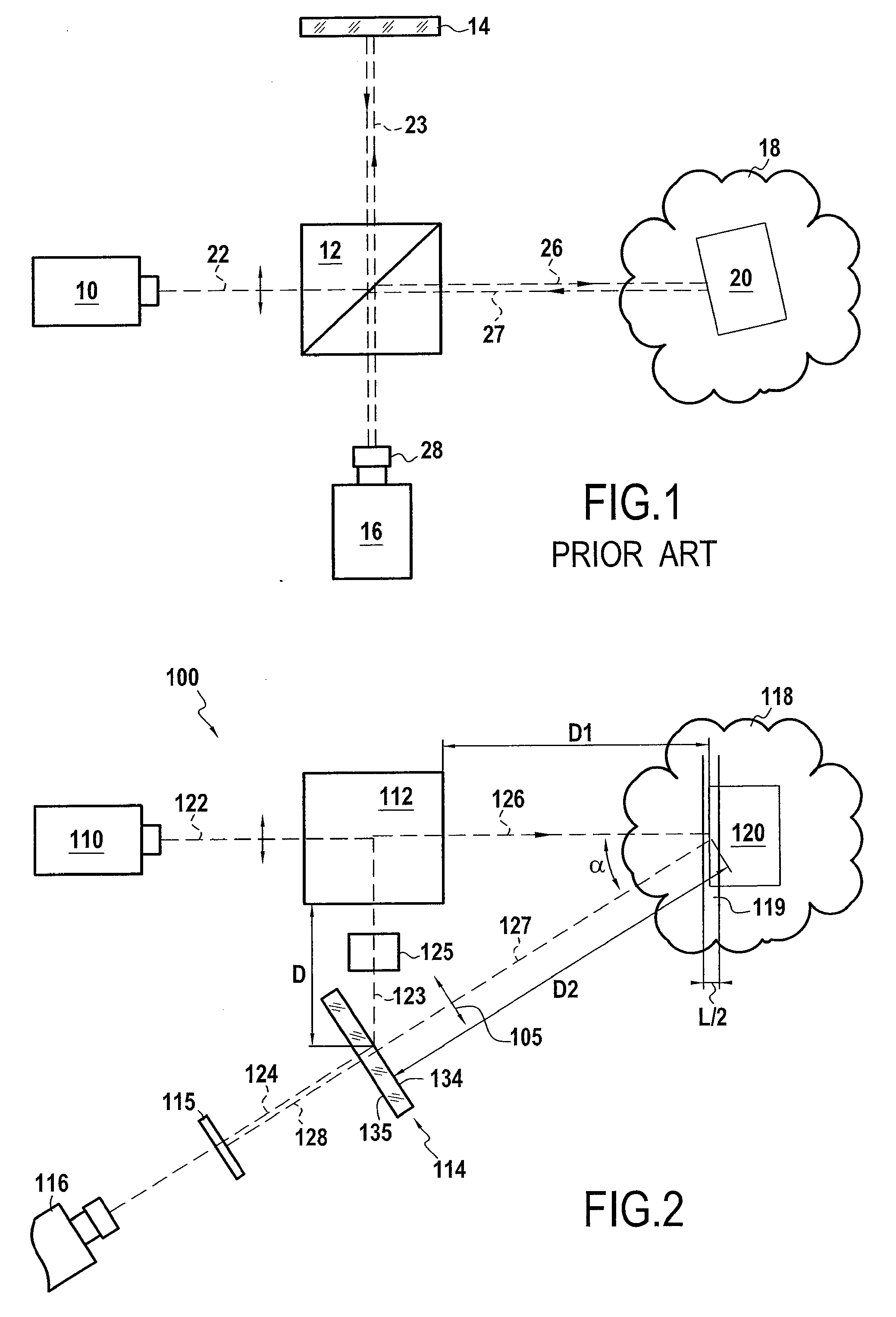
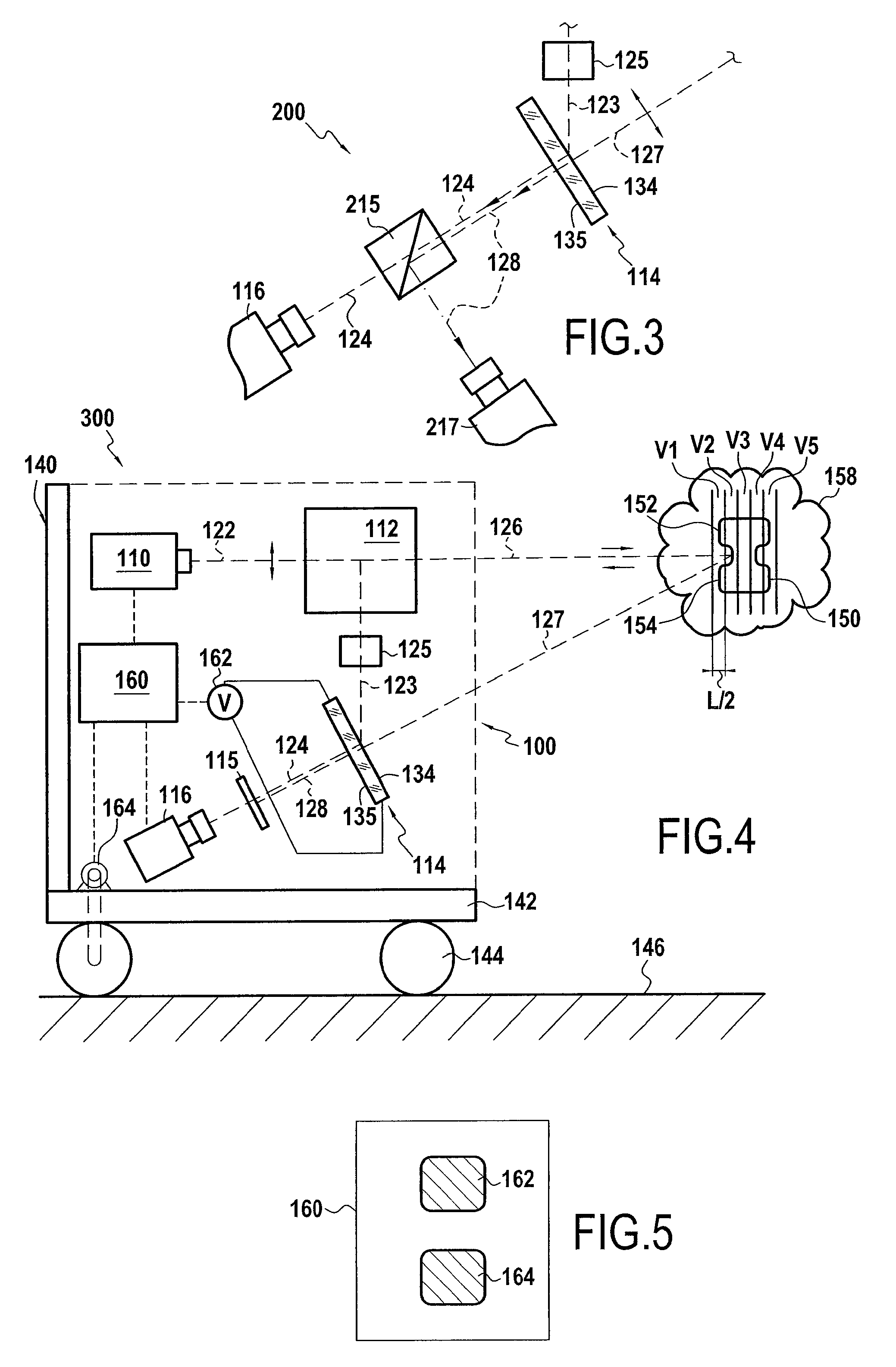
[0067]A sensor 100 of the invention is shown in FIG. 2.

[0068]The sensor 100 comprises a light source 110, a beam-splitter cube 112, a photorefractive crystal 114, a polarizer 115, and a detector 116.

[0069]The light source 110 is a laser source that emits a source beam 122 towards an object 120 for measurement. In the context of the invention, the light source could equally well be a laser, a laser diode, LED, etc.

[0070]The object 120 is situated in a diffusing medium 118, which may be an atmosphere charged with particles such as a fog or the atmosphere on a rainy day, or it could be a living tissue or other tissue (where measurement is also possible, a fortiori, when the medium 118 is not a diffusing medium). The splitter cube 112 lies on the path of the source beam 122 and it splits it into two beams:

[0071]a reference beam 123 that is deflected through 90° relative to the direction of the source beam 122; and

[0072]an incident beam 126 that is not deflected and that continues its jo...


PUM


Abstract

A sensor for remotely detecting an object, the sensor comprising:
    • a light source having a coherence length that is short relative to the distance between the sensor and the object;
    • a splitter splitting the emitted light beam into an incident beam and a reference beam;
    • a photorefractive crystal recording a hologram on interfering reception of the reference beam and of the reflected beam reflected by an object illuminated by the incident beam, and playing back the hologram in a diffracted beam that is re-emitted by the crystal by anisotropic diffraction under the effect of the reference beam;
    • a detector recording information on receiving the diffracted beam; and
    • a polarizing filter that eliminates the major fraction of the reflected beam as transmitted by the crystal on receiving the reflected beam; such that the detector receives only the diffracted beam from the crystal. Both the sensor and imaging systems incorporating the sensor enable measurements to be made through diffusing media.

Description

FIELD OF THE INVENTION[0001]The invention relates to remotely measuring the position and / or the shape of an object, in particular when the object is situated in a diffusing medium. Three applications are envisaged more particularly:[0002]on a large scale, measuring the movements and / or the distances of targets (whether co-operating or otherwise), in particular in unfavorable weather conditions;[0003]on a medium scale, for a vehicle traveling on a road, detecting and / or identifying obstacles or other vehicles through fog or rain; and[0004]on a small scale, measuring cellular structures within biological tissues.BACKGROUND OF THE INVENTION[0005]Various technological solutions are known for remotely measuring the position of an object. Some are partially suitable for making measurements in a diffusing medium.[0006]Firstly, at a large scale, it is known to make use of theodolites for measuring the relative positions of objects. Such sensors consist in emitting an infrared laser beam to ...

Claims


Application Information

Patent Timeline
IPC IPC(8): G01B9/021
CPCG01N21/453G03H2260/36G03H1/0005G03H1/04G03H2001/0038G03H2001/0083G03H2001/026G03H2001/0268G03H2001/0467G03H2001/2244G03H2001/2276G03H2210/63G03H2222/31G03H2223/26G01N21/4795
Inventor TAILLADE, FREDERICBELIN, ETIENNE
Owner LETAT FR REPRESENTE PAR LE LABE CENT DES PONTS & CHAUSEES
Why Eureka
Try Eureka