Vapor recovery gas pressure boosters and methods and systems for using same

a technology of gas pressure booster and vapor recovery, which is applied in the direction of positive displacement liquid engine, piston pump, machine/engine, etc., can solve the problems of insufficient quantity of compressed air to drive the compression section, inability to locate crankcase-driven machines and engine drives, and inability to provide compressed air in sufficient quantity

Inactive Publication Date: 2010-06-24
MIDWEST PRESSURE SYST
View PDF2 Cites 27 Cited by
  • Summary
  • Abstract
  • Description
  • Claims
  • Application Information

AI Technical Summary

Benefits of technology

[0035]In a further alternative embodiment, useful with either the gas booster system or method for using it, two communicating three-way valves may be provided, with one side of the valves connecting the boost cylinder to a vapor line, and the other side of the valves connecting the boost cylinder to a low pressure gas line. In this embodiment, the need for any check valves or low pressure line connections to the boost cylinder may be eliminated.

Problems solved by technology

For many applications, such as natural gas compression for pipelines, refueling natural gas vehicles and vapor recovery from gas wells, compressed air is either not available or available in sufficient quantity to drive the compression section.
Electricity may also not be present, either at all or in sufficient quantities to operate a crankcase or hydraulic drive.
There is also frequently a lack of space to locate crankcase-driven machines and engine drives.
In many cases, such as gas wells or remote pipeline compressor stations, no electricity is available (all equipment may be run off of natural gas).
The wellhead gas at a much higher pressure may be reduced in pressure when it enters the sales line, where substantial energy is lost.
These fugitive emissions of volatile organic compounds are a safety and environmental hazard.
The additional stages of compression require more equipment and cooling between the stages resulting in additional capital costs and energy consumption.

Method used


Image

  • Vapor recovery gas pressure boosters and methods and systems for using same
  • Vapor recovery gas pressure boosters and methods and systems for using same
  • Vapor recovery gas pressure boosters and methods and systems for using same

Examples


Embodiment Construction

[0041]Set forth below is a description of what are currently believed to be the preferred embodiments and / or best examples of the invention claimed. Future and present alternatives and modifications to these preferred embodiments are contemplated. Any alternatives or modifications which make insubstantial changes in function, in purpose, in structure or in result are intended to be covered by the claims of this patent.

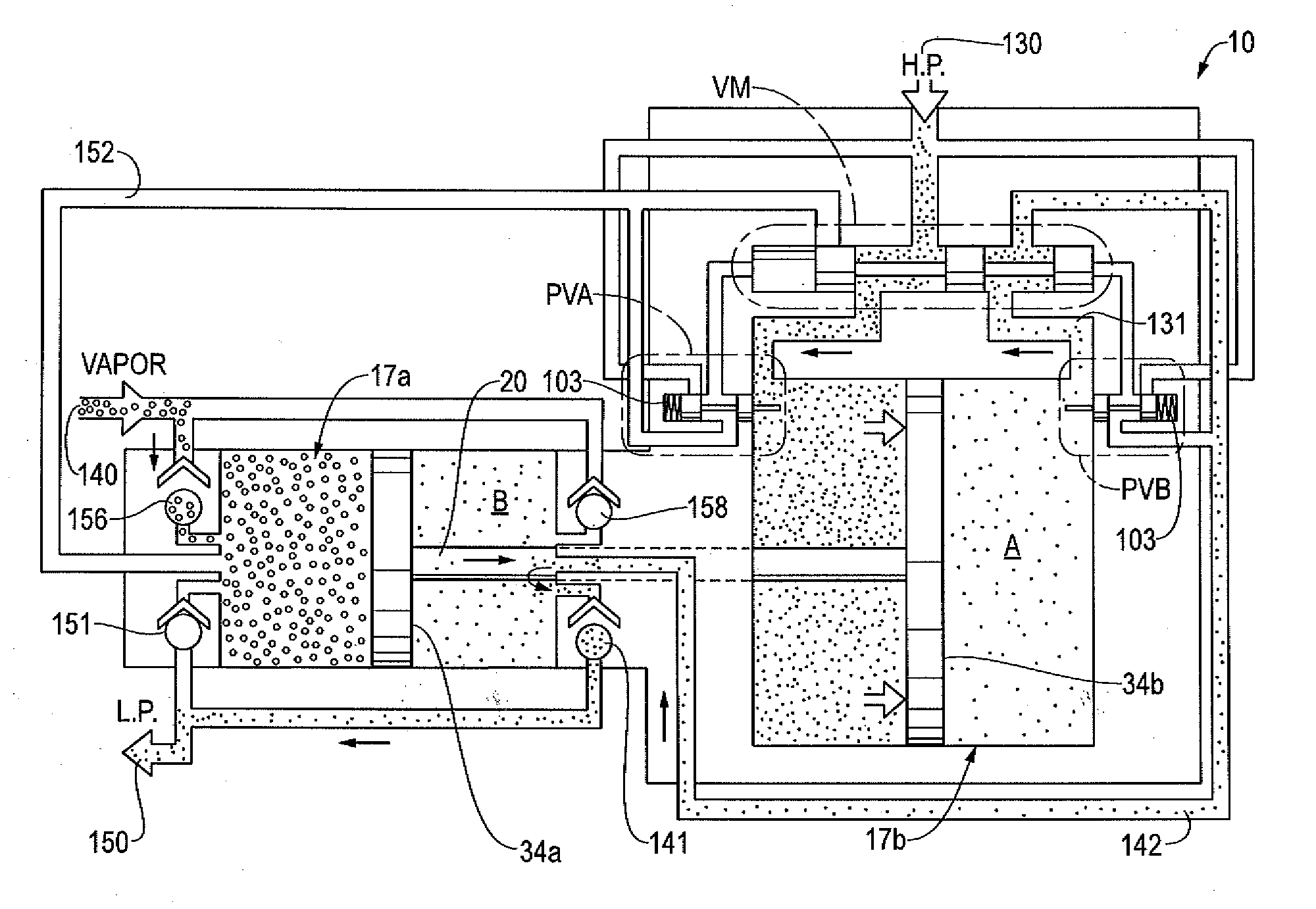
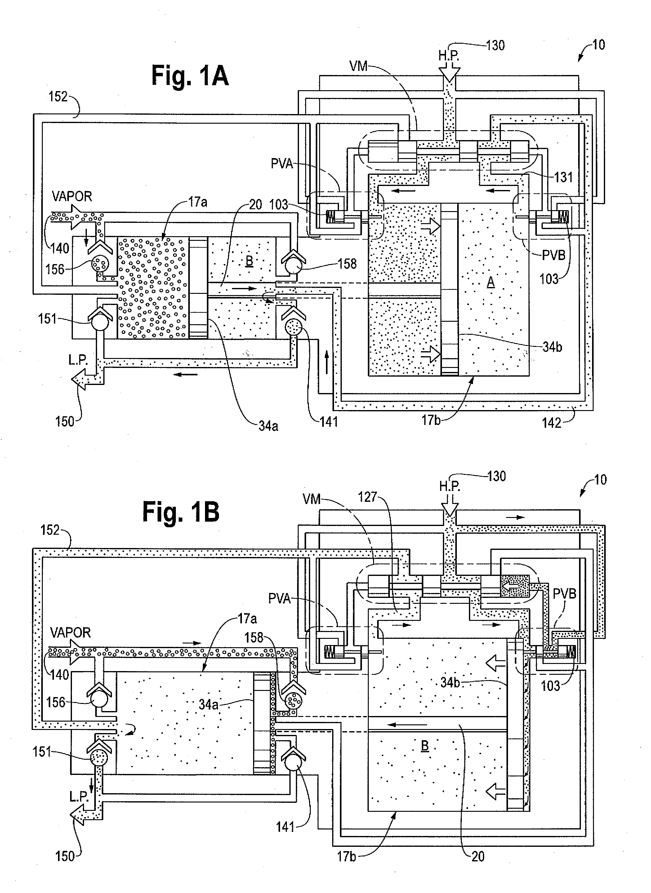
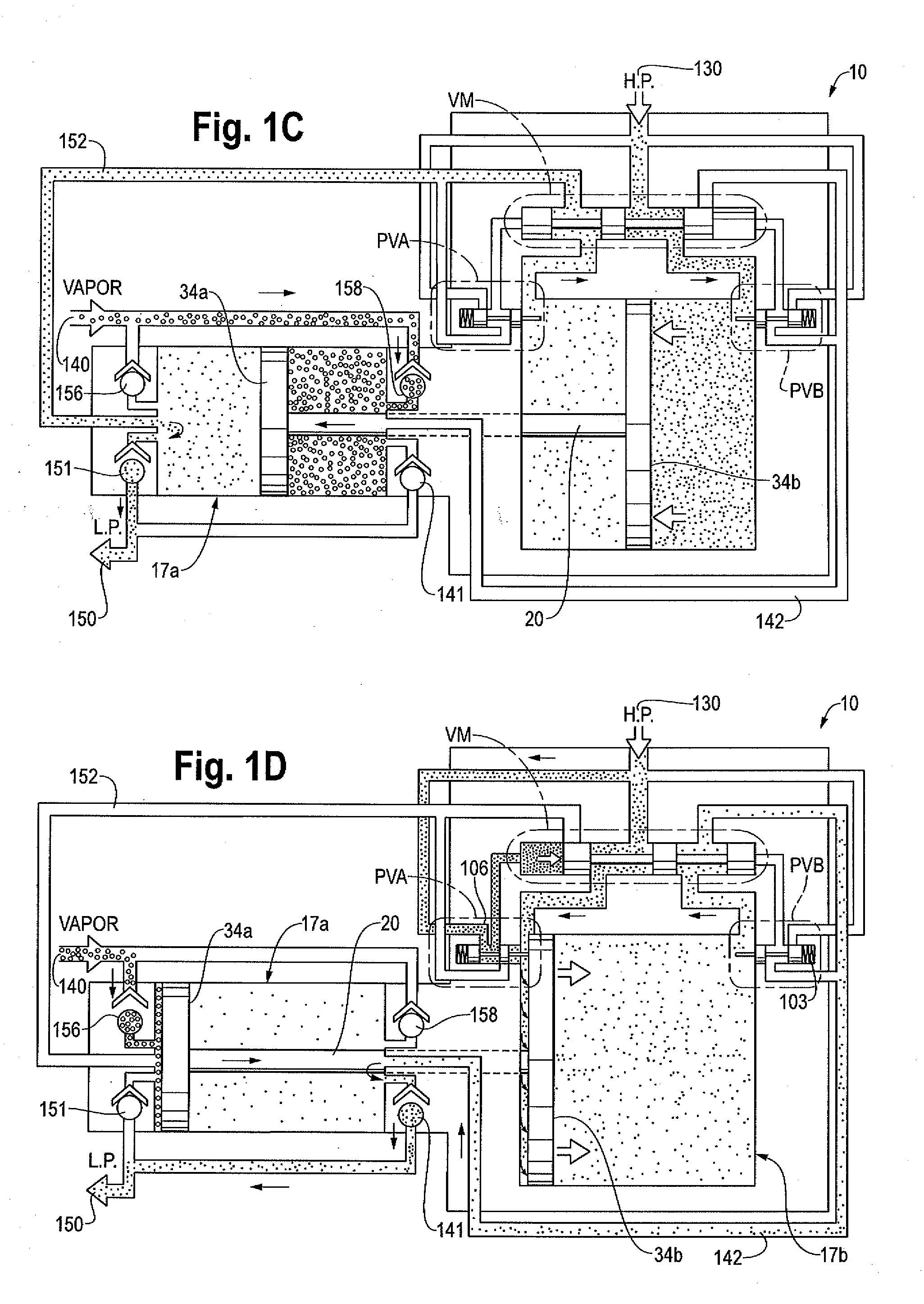
[0042]Referring now to FIGS. 1A-1D, the operation of a preferred embodiment of the present invention, designated generally as gas pressure booster system 10, will now be described. Referring first to FIG. 1A, gas pressure booster system 10 generally includes boost cylinder 17a, drive cylinder 17b, and a valving system connecting pilot valves PVA and PVB to a valve manifold / 4-way valve designated generally VM, as described below. The valve manifold and all pilot connections are connected to a sink and a source of pressurized gas, as also explained below. A gas vapor sou...


PUM


Abstract

A gas pressure booster and a method for using it, which recovers fugitive gas emissions such as at atmospheric pressure, boosts them such as to the pressure level of the low pressure gas sink, and returns them to, e.g., the low pressure gas sink, in a single stage of compression. No electricity or cooling water is required. All gas used to drive the vapor recovery booster may be recovered and vented to the low pressure gas sink.
In one preferred embodiment, the gas pressure booster includes a drive cylinder and a boost cylinder interconnected by reciprocating drive and boost pistons. The drive piston supplies force powered by a first gas stream within the drive cylinder which exhausts to a second gas stream at a lower pressure. Fugitive gas emissions may be captured and transported to the lower pressure second gas stream to eliminate gas discharged to atmosphere. The need for boosting a gas multiple ratios is eliminated, as the pressure of the fugitive emission vapor is equalized to the low pressure gas sink at the end of the piston suction stroke. Preferably, a four-way valve operating on differential gas pressure may be used to automatically actuate the reciprocating piston.

Description

BACKGROUND OF THE INVENTION[0001]The present invention relates to gas pressure boosters. More specifically, the present relates to gas pressure boosters and methods and systems for using them in which fugitive emissions are captured, and in which the need for staged gas compression is largely eliminated.[0002]Gas pressure boosters may include a drive system which provides the energy required to operate a compression system, and a compression system which elevates the gas pressure. The drive systems may include: a crankcase driven by an electric motor or an engine; a turbine drive; a hydraulic piston driven by an electric motor or an engine; and a pneumatic piston driven by air or gas pressure.[0003]The compression system may include:[0004]a reciprocating piston (providing moderate boost ratios and flowrates, suitability for high operating pressures, low to moderate cost, a compact design, rod seal leakage and vibration, and a moderate operating life for the seals, especially non-lub...

Claims


Application Information

Patent Timeline
Patent Type & Authority Applications(United States)
IPC IPC(8): F04B35/02
CPCF04B35/004F04B25/02
Inventor VOGT, ROBERT A.
Owner MIDWEST PRESSURE SYST
Why Eureka
Try Eureka