Valveless micropump

a valveless, micropump technology, applied in the direction of machines/engines, liquid fuel engines, positive displacement liquid engines, etc., can solve the problems of short-lived micropump, large time-consuming and labor-intensive testing, and the geometry of the channel combining the diffuser/nozzle elements, etc., to achieve less flow resistance

Inactive Publication Date: 2010-06-24
NAT UNIV CORP KYUSHU INST OF TECH (JP)
View PDF5 Cites 13 Cited by
  • Summary
  • Abstract
  • Description
  • Claims
  • Application Information

AI Technical Summary

Benefits of technology

[0021]With the valveless micropump constructed as stated earlier, the diffuser-shape channel is made asymmetric geometry taking on different flow resistance depending on which direction the fluid is flowing. More especially, even with the same force to squeeze the fluid, the flow rate will get different in the diffuser stream and the nozzle stream opposite the diffuser stream. With the nozzle stream less in flow resistance than the diffuser stream, the fluid begins moving in the direction more readily allowable to flow, or nozzle direction when the oscillatory flow is applied thereto, thereby developing the pumping function to transfer the fluid. As the nozzle direction refers to the direction in which the channel becomes gradually less in transverse section, the pressure variation occurring in the fluid inside the volumetrically variable chamber changes into the oscillatory flow to force the fluid to flow with smooth in the nozzle direction. Upon energization of the oscillation activator such as piezoelectric element, thus, the fluid is forced in the direction of nozzle stream, or from the spread channel to reduced channel. Here, the diffuser stream refers to the flow from the reduced channel into the spread channel, whereas the nozzle stream refers to the flow from the spread channel into the reduced channel.

Problems solved by technology

The gene tests take considerable times, for example several days for current technology.
To cope with this, it remains a major challenge to develop analyzers very small in construction called μ TAS short for Micro Total Analysis System or Lab-on-a chip.
This causes any damage to moving parts and turning components combined in the micropump, raising a major issue of having the micropump itself short-lived.
Moreover, the micropump with mechanical components of intricate configuration results in increasing the number of the parts desired, which would give rise to the questions of several more chores to produce many parts and members with precision and assemble them together.
With the micropumps relying on the differential resistance in the fluid channel, it has already been found that the channel geometry combining together the diffuser / nozzle elements constructed as stated earlier is worse in efficiency for the reason their mutual effects get cancelled each other out in relation with the variation in flowing direction of the oscillatory fluid.

Method used


Image

  • Valveless micropump
  • Valveless micropump
  • Valveless micropump

Examples


Embodiment Construction

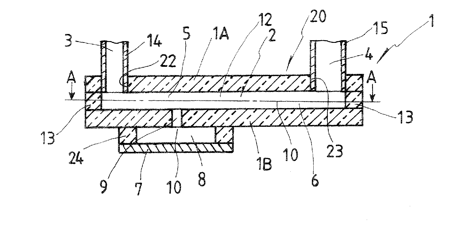
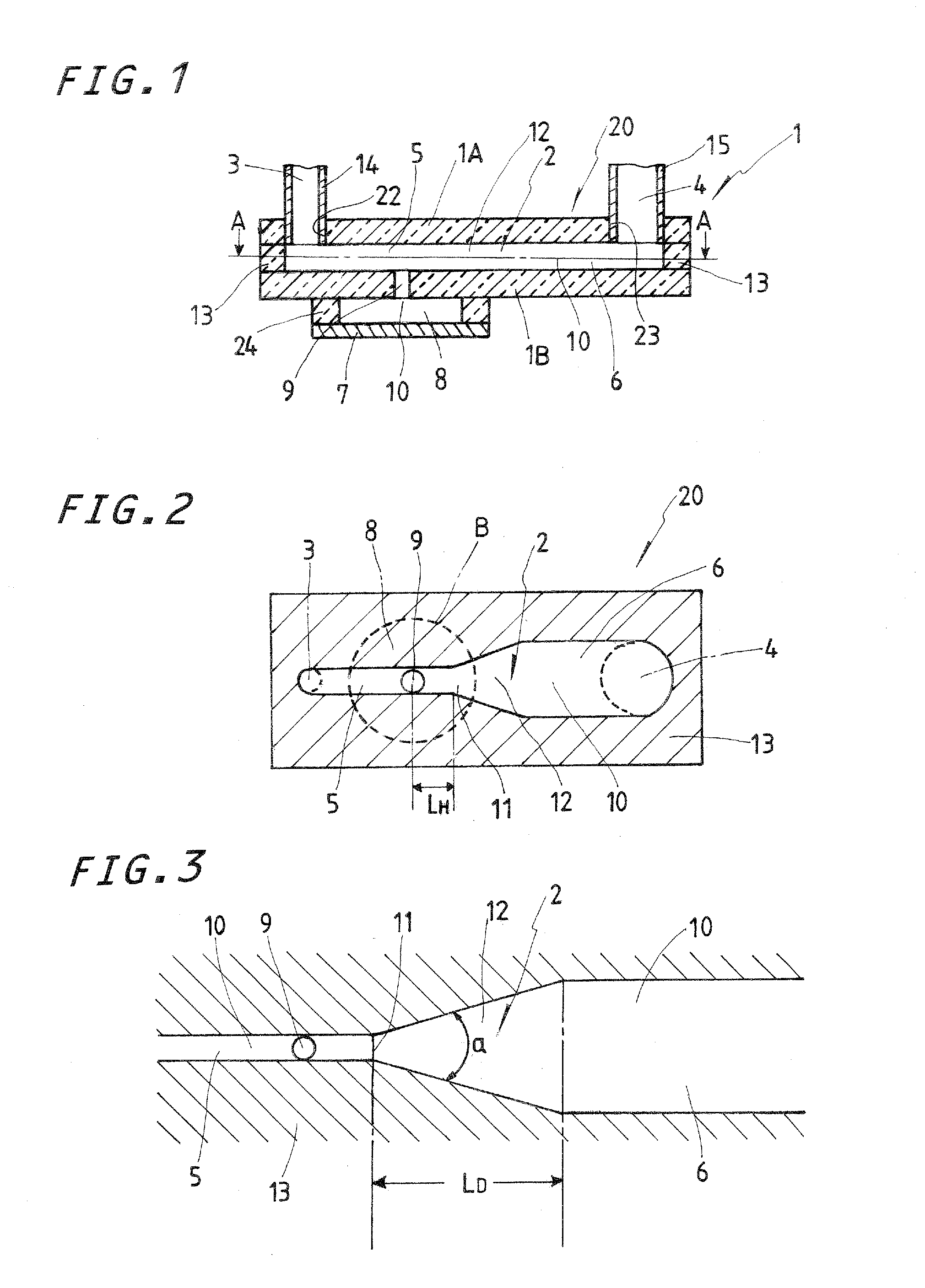
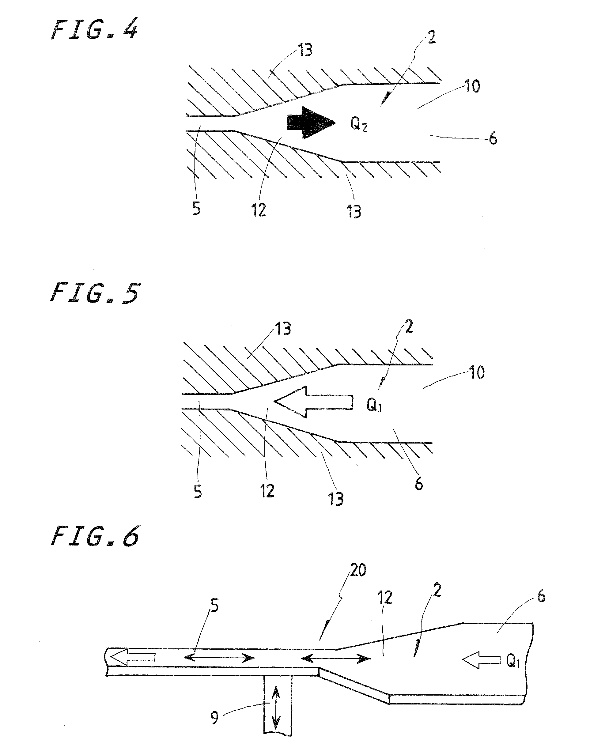
[0048]A preferred embodiment of a micropump constructed according to the present invention will be explained below with reference to the accompanying drawings. The micropump of the present invention features the specific configuration of a channel 2 in which a stream of flow is generated with using a difference in flow resistance across an asymmetric diffuser / nozzle shape. Thus, the micropump of the present invention has no moving part including valves. This constructional feature in turn will help avoid a major issue of any damage of moving parts, and so on inherent in conventional micropumps, thereby having the micropump long-lived. With the micropump of the present invention constructed as shown in FIG. 1, the channel 2 made of a channel-formative member 1 of, for example acryl plate, stainless steel plate, and so on is modified in shape somewhere in the way into an asymmetric diffuser-shape channel 12 made of stainless steel plate. The diffuser-shape channel 12 is flanked in the...


PUM


Abstract

A valveless micropump for transforming a pressure variation of fluid in a volume variation chamber (8) into an oscillatory flow of fluid (10) by means of a piezoelectric element (7), making the fluid (10) to flow smoothly in channels (5, 6). A channel (2) is formed as an asymmetric diffuser-shaped channel (12) having a narrow channel (5) on the diffuser inlet (3) side and a wide channel (6) on the diffuser outlet (4) side, and the volume variation chamber (8) provided with the piezoelectric element (7) is communicated with the narrow channel (5). Vibration generated by applying a voltage to the piezoelectric element (7) causes a pressure variation of the fluid in the volume variation chamber (8) to generate a nozzle flow. The fluid (10) is made to flow smoothly from the wide channel (6) to the narrow channel (5) by the nozzle flow.

Description

FIELD OF THE INVENTION[0001]The present invention relates a miniature pump having no-moving-parts valves, or valveless micropump, which is dedicated to force fluids into a flow channel in, for example, medical and chemical applications.BACKGROUND AND REVIEW OF RELATED TECHNOLOGY[0002]A lot of research is nowadays going on in the pipeline to develop designer drugs or therapeutics based on genes after the completion of the human DNA sequence of entire human genomes. Explorations into drug design and gene therapies have need of gene tests for individual patients. The gene tests take considerable times, for example several days for current technology. To cope with this, it remains a major challenge to develop analyzers very small in construction called μ TAS short for Micro Total Analysis System or Lab-on-a chip. The μ TAS refers to a microscopic system in which laboratory functions including chemical reaction, metering, pumping, and so on are all integrated on a single chip to make it ...

Claims


Application Information

Patent Timeline
Patent Type & Authority Applications(United States)
IPC IPC(8): F04B43/04B81B3/00F04B43/02
CPCF04B53/1077F04B43/046
Inventor MIYAZAKI, KOJITANAKA, SEIICHISHIMOOKA, HIROYUKITSUKAMOTO, HIROSHI
Owner NAT UNIV CORP KYUSHU INST OF TECH (JP)
Why Eureka
Try Eureka