
Eureka
For R&D, Eureka makes reading and utilizing patents & technical documents easy.
Eureka AIR
Designed for self-driven R&D workflows. Generate viable solutions, solve complex R&D challenges, empower your innovation with AI.

Eureka Materials
Designed for material experts only. Revolutionize your material R&D, from search, analyze, to developing new materials.

TechResearch
Generate reliable direction feasibility study reports for your R&D in just a few steps.

TechSeek
Discover and master advanced knowledge NOW. Basics, ideas, possibilities, all at once.

TechMind
As an expert in R&D Theories, TechMind can generates customized viable solutions instantly.

TechRisk
Analyze your overall solution with one click, know your potential R&D risks in advance.

TechMonitor
Get weekly tech updates, stay abreast of the latest tech innovations and key insights.
Method and system for enhancing heat transfer of turbine engine components
- Summary
- Abstract
- Description
- Claims
- Application Information
AI Technical Summary
Benefits of technology
Problems solved by technology
Method used
Image

Examples
Embodiment Construction
[0019]In one embodiment, the present disclosure is generally applicable to metal components that are protected from a thermally hostile environment by a thermal barrier coating (TBC) system. Notable examples of such components include the high and low pressure turbine nozzles (vanes), shrouds, combustor liners, transition pieces, turbine frame and augmentor hardware of gas turbine engines. While this disclosure is particularly applicable to turbine engine components, the teachings of this disclosure are generally applicable to any component on which a thermal barrier may be used to thermally insulate the component from its environment.
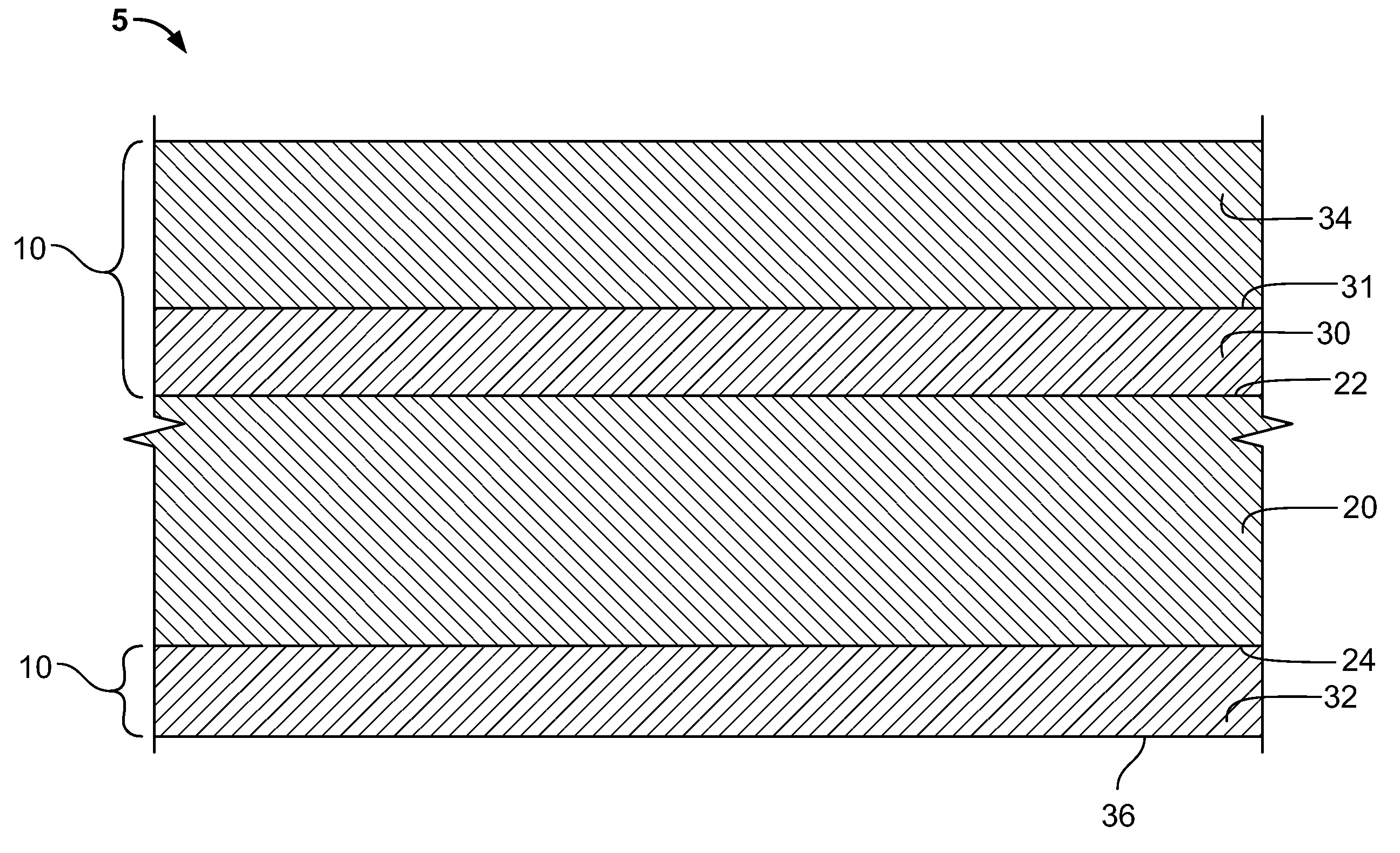
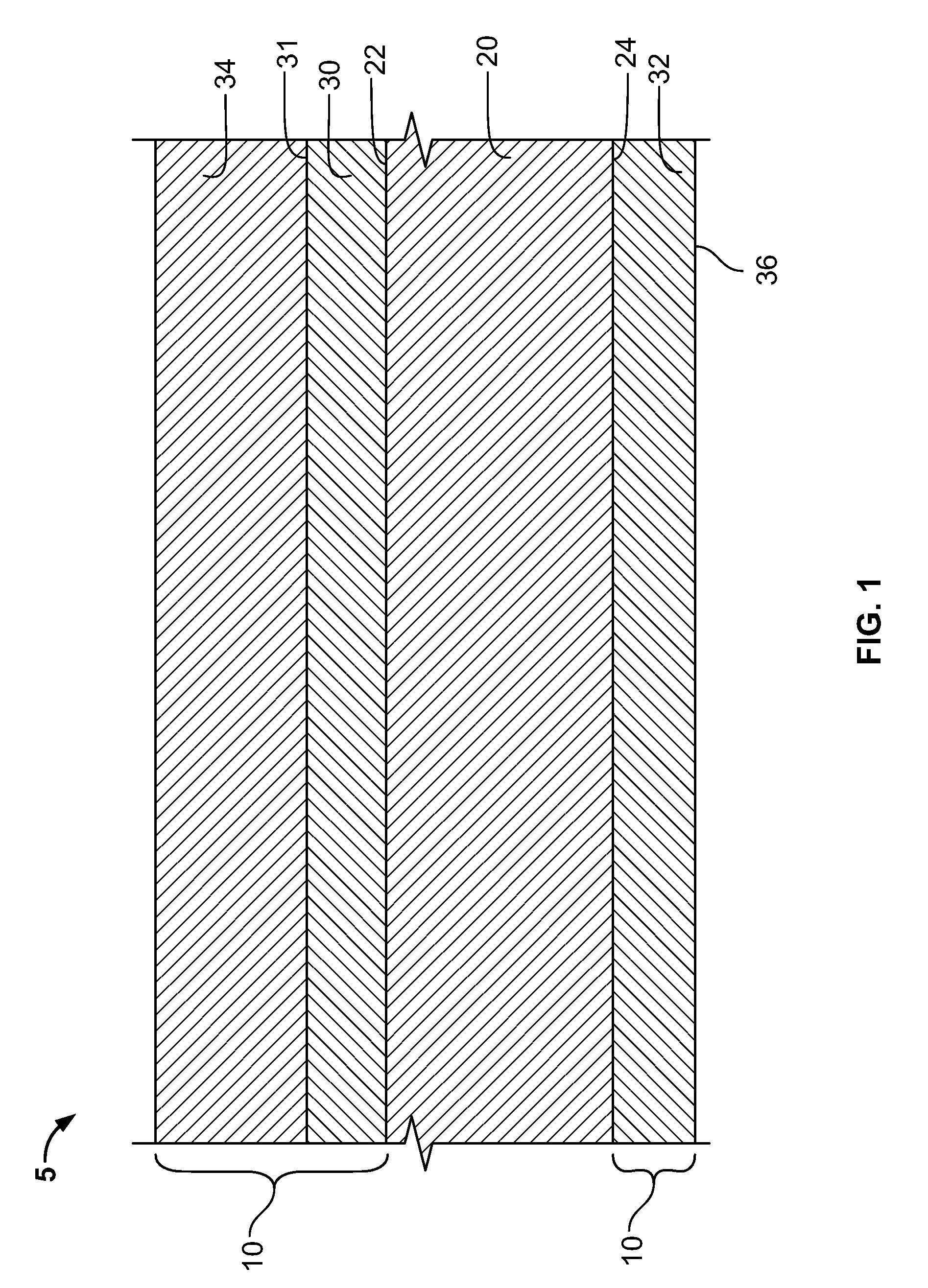
[0020]FIG. 1 shows a partial cross-section of a turbine engine component 5 having a TBC system (coating system) 10 in accordance with the present disclosure. The turbine engine component 5 includes a substrate 20 upon which the coating system 10 is deposited. The substrate 20 includes a first surface 22 and an opposing second surface 24. The first surf...
PUM
| Property | Measurement | Unit |
|---|---|---|
| Thickness | aaaaa | aaaaa |
| Thickness | aaaaa | aaaaa |
| Percent by mass | aaaaa | aaaaa |
Abstract
Description
Claims
Application Information
 - R&D Engineer
- R&D Manager
- IP Professional
- Industry Leading Data Capabilities
- Powerful AI technology
- Patent DNA Extraction
Browse by: Latest US Patents, China's latest patents, Technical Efficacy Thesaurus, Application Domain, Technology Topic, Popular Technical Reports.
© 2024 PatSnap. All rights reserved.Legal|Privacy policy|Modern Slavery Act Transparency Statement|Sitemap|About US| Contact US: help@patsnap.com