
Vehicle provided with engine and engine

a technology for vehicles and engines, applied in the direction of machines/engines, gearing details, auxilaries, etc., can solve the problems of increasing the number of parts and cost, and the oil amount in the oil pan becomes insufficient, and achieves the effect of affecting the state of the oil circulation

Inactive Publication Date: 2010-07-01
KAWASAKI HEAVY IND LTD
View PDF4 Cites 0 Cited by
  • Summary
  • Abstract
  • Description
  • Claims
  • Application Information

AI Technical Summary

Benefits of technology

[0007]The present invention is achieved in consideration with the above problems, and an object of the present invention is to provide a vehicle for always leaving oil in an oil pan within a range of a predetermined level and preventing excessive gathering of the oil in a chamber other than the oil pan, irrespective of a driving situation of the vehicle such as driving on a downward slope, idling or driving on an upward slope, thereby to maintain a favorable state of an oil circulation.
[0009]According to the above configuration, at the time of driving the vehicle, it is possible to promptly return the oil in the crank chamber to the oil pan of the transmission chamber via the first oil communication hole or opening, the rotor housing chamber (such as the generator chamber) and the second oil communication hole or opening. Moreover, even at the time of driving the vehicle inclined on the cylinder inclination side (such as forward), it is possible to leave a predetermined amount of the oil in the oil pan. Therefore, it is possible to prevent air entrainment by the oil pump.
[0011]According to the above configuration, at the time of driving the vehicle inclined by the predetermined angle in the cylinder inclination direction, a flow of the oil from the crank chamber into the cylinder is suppressed. Therefore, it is possible to maintain smooth sliding of a piston without disturbing movement of the piston in the cylinder by the oil.
[0013]According to the above configuration, it is possible to actively and promptly discharge the oil in the crank chamber from the oil discharge hole or opening by utilizing the rotation of the crankshaft in addition to oil discharge from the first oil communication hole or opening. By forming the ventilation hole or opening, it is possible to absorb a pressure change in the crank chamber so as to facilitate oil coming in and out of the crank chamber.

Problems solved by technology

However, in a case where the scavenging pump is provided, the number of parts and cost are increased.
However, depending on a driving situation of the vehicle, for example when the vehicle is inclined forward, rearward, leftward or rightward at the time of driving on a slope or the like, there is sometimes a case where an oil amount in the oil pan becomes insufficient due to movement of the oil in the oil pan, or too much oil is gathered in a chamber other than the oil pan.

Method used


Image

  • Vehicle provided with engine and engine
  • Vehicle provided with engine and engine
  • Vehicle provided with engine and engine

Examples


first embodiment

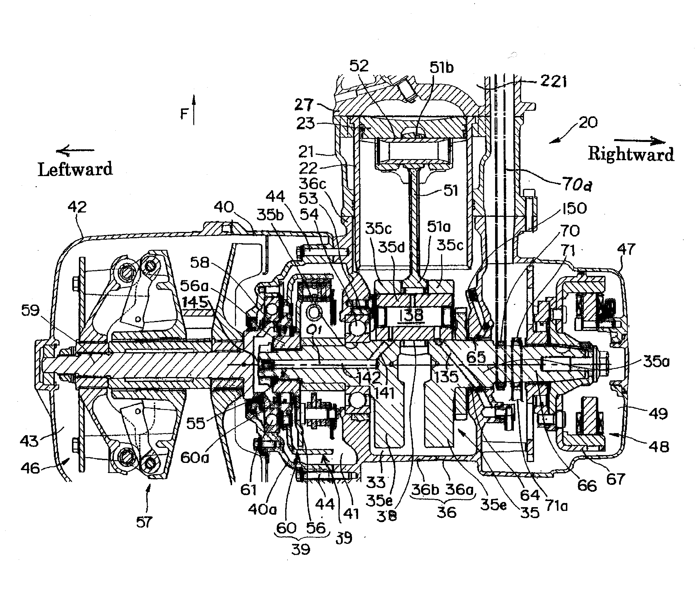
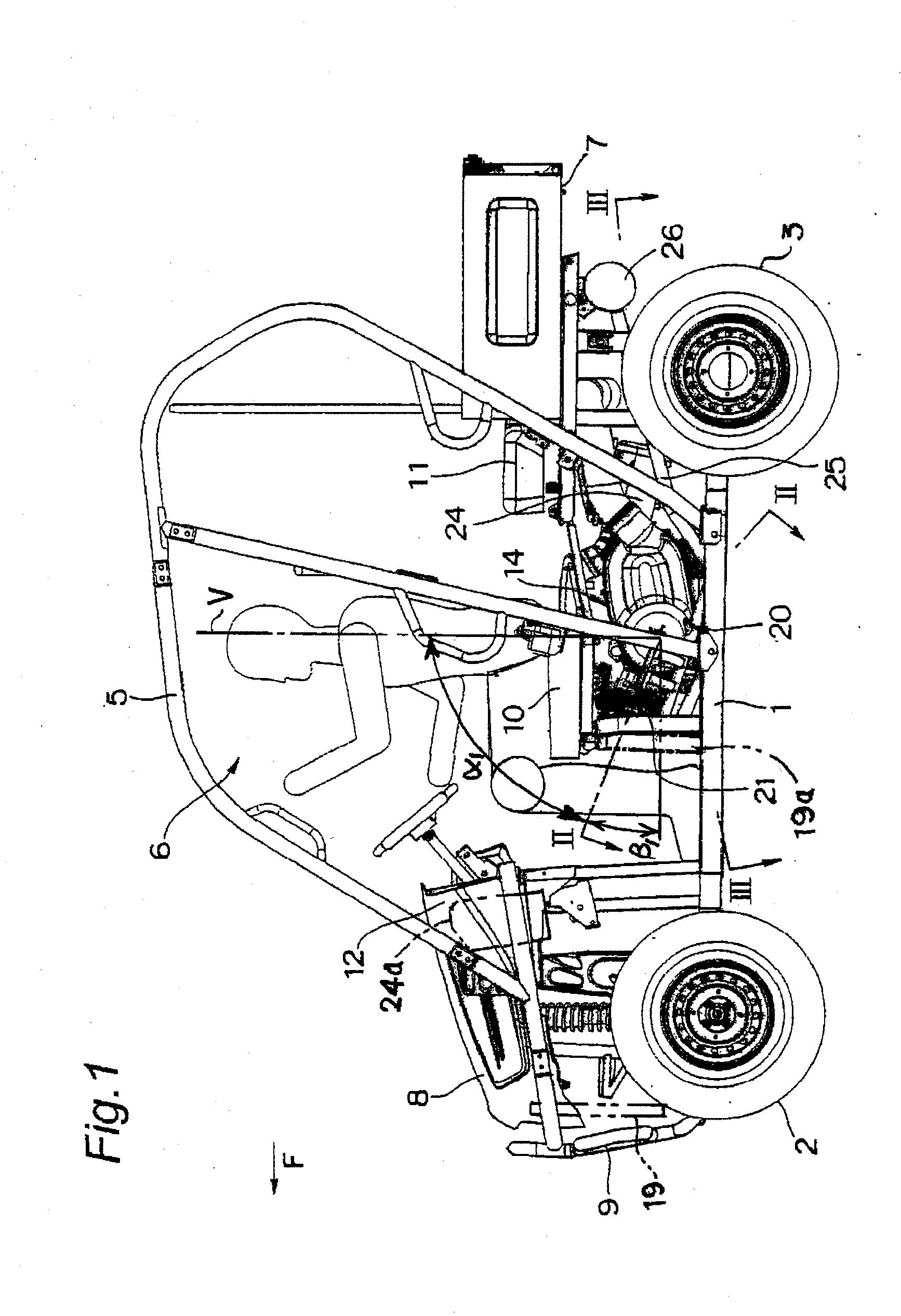
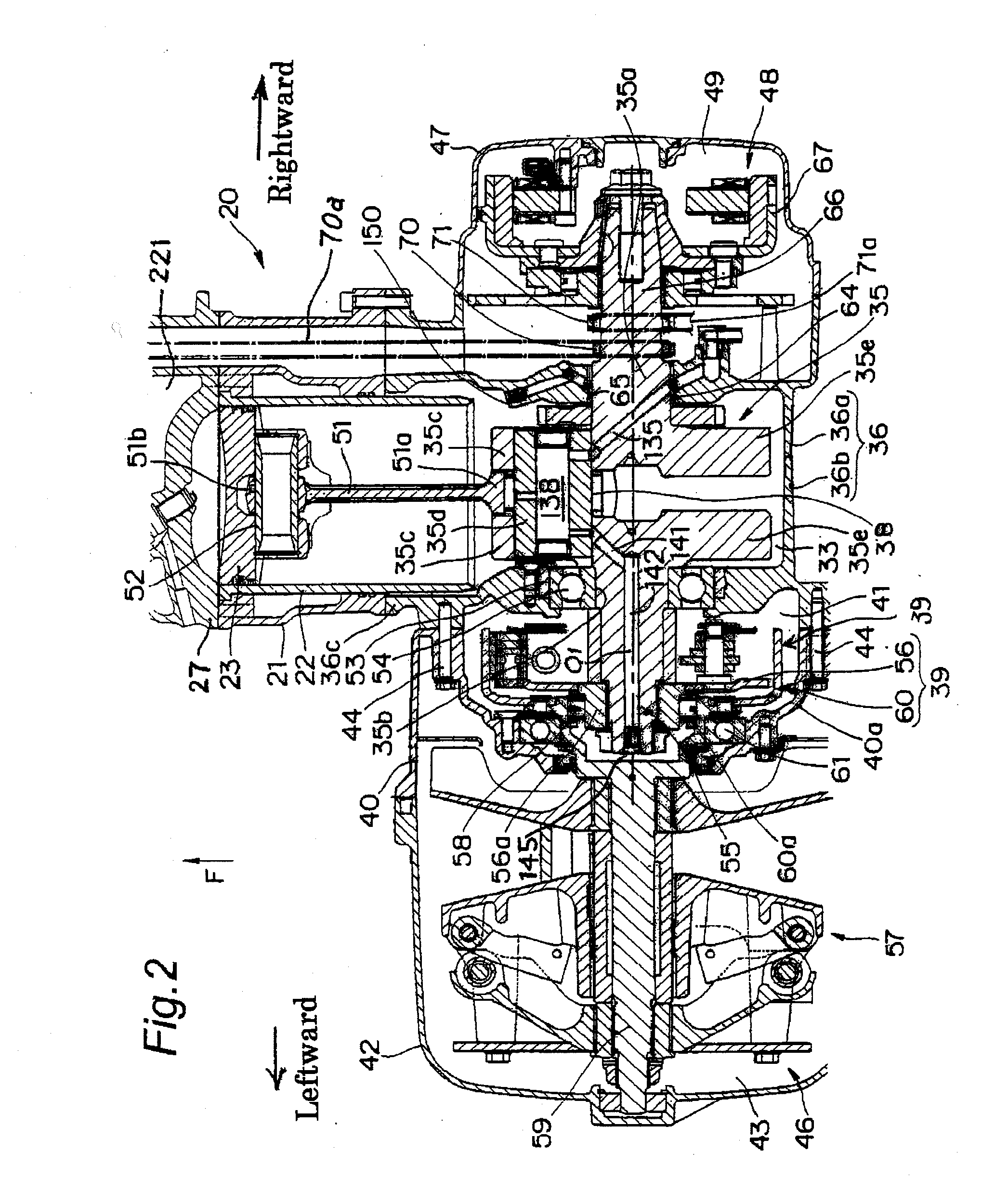
[0037]FIGS. 1 to 8 show a first embodiment of a vehicle engine according to the present invention. One embodiment of the present invention will be described with reference to the figures.

[0038]FIG. 1 is a partially cut left side view showing a small-sized four-wheeled vehicle for irregular terrain (so-called utility vehicle) provided with a vehicle engine according to the present invention. In FIG. 1, the four-wheeled vehicle is provided with a pair of left and right front wheels 2 in a front part of a vehicle frame 1, a pair of left and right rear wheels 3 in a rear part of the vehicle frame 1, a cabin 6 surrounded by a cabin frame 5 between the front wheels 2 and the rear wheels 3, a loading platform 7 on the rear side of the cabin 6, a bonnet 8, a bumper 9 and the like on the front side of the cabin 6, and fenders (not shown) respectively on the upper side of the front wheels 2 and the rear wheels 3.

[0039]A front seat 10 formed in a bench shape is installed in a front half part i...

second embodiment

[0083]FIGS. 9 and 10 show a second embodiment of the present invention. FIG. 9 is a left side view of the left crank case member 36b. A basic structure is the same as the first embodiment. In addition to this, an oil discharge hole or opening 160 and a ventilation hole or opening 161 are provided in a bottom wall 33d and a side wall of the crank chamber 33. It should be noted that the same parts and portions as the first embodiment are given the same reference symbols (numerals). An area in which cross-hatching is drawn in FIG. 10 indicates a section of the oil.

[0084]FIG. 9 is the left side view of the left crank case member 36b, and FIG. 10 is a sectional view taken along line X-X in FIG. 9. In FIG. 10, the oil discharge hole or opening 160 providing communication between the crank chamber 33 and the clutch chamber 41 is formed in a rear part of the bottom wall 33d of the crank chamber 33, and the ventilation hole or opening 161 providing communication between the crank chamber 33 ...

third embodiment

[0088]FIG. 11 shows a third embodiment of a vehicle engine according to the present invention. The engine 20 is a V-type two-cylinder engine in which a front cylinder 21a inclined forward and a rear cylinder inclined rearward are arranged in an upper end of a front part of the crank case 36 so as to open upward in a V-type arrangement. A forward inclination angle α1 of a center line C1 of the front cylinder 21a relative to the vertical direction (vertical line V) is set to be 50°, and a rearward inclination angle α2 of a center line C2 of the rear cylinder 21b relative to the vertical direction (vertical line V) is set to be 40°. Therefore, an angle between the center line C1 of the front cylinder 21a and the center line C2 of the rear cylinder 21b (V-type opening angle α1+α2) is set to be 90°.

[0089]The third embodiment has the same configuration as the first embodiment except the front and rear cylinders 21a and 21b of the V-type arrangement. The same parts are given the same refer...


PUM


Abstract

A center line of a cylinder of an engine of the present invention is inclined by an inclination angle of 60° or more relative to a vertical direction. The engine is provided with a first oil communication hole or opening providing communication between a crank chamber and a rotor housing chamber so as to distribute oil, and a second oil communication hole or opening providing communication between the rotor housing chamber and a transmission chamber so as to distribute the oil. The second oil communication hole opening is arranged at a position where the oil remains in an oil pan when the vehicle is inclined.

Description

BACKGROUND OF THE INVENTION[0001]1. Field of the Invention[0002]The present invention relates to a vehicle provided with an engine and the engine, more particularly to a vehicle provided with an engine including an oil circulation route having an oil pan in a lower end of a transmission chamber of a crank case, and the engine.[0003]2. Description of the Prior Art[0004]One example of the oil circulation route in the vehicle engine having the oil pan in the lower end of the transmission chamber will be briefly described. Oil suctioned from the oil pan by an oil pump is supplied to oil feeding points of the engine such as a bearing of a crankshaft, a crank pin, a piston, a clutch, a generator, a cam shaft of a cylinder head, and a transmission shaft via oil passages for oil supply and then utilized for lubrication and / or cooling at the oil feeding points. The supplied (used) oil is returned to the oil pan of the transmission chamber via oil passages for oil return of the points, a cran...

Claims


Application Information

Patent Timeline
Patent Type & Authority Applications(United States)
IPC IPC(8): F01M1/02F01M11/00F02F7/00F16H57/037F16H57/04
CPCF01M11/02
Inventor TAKANO, KIYOHITO
Owner KAWASAKI HEAVY IND LTD
Learn More