

Solar cell package type with surface mount technology structure
- Summary
- Abstract
- Description
- Claims
- Application Information
AI Technical Summary
Benefits of technology
Problems solved by technology
Method used
Image

Examples
Embodiment Construction
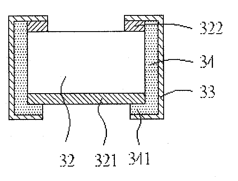
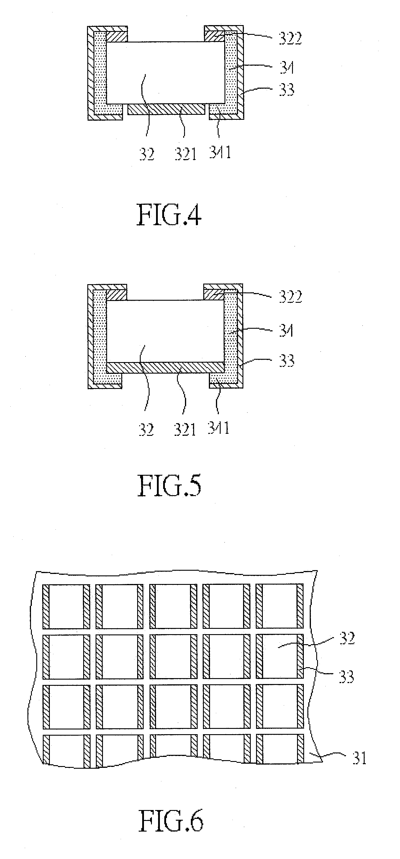
[0018]First of all, referring to FIGS. 4 and 5, the package type in accordance with the invention includes a solar cell 32, at least one connection electric terminal 33 (two connection electric terminals 33 illustrated in the drawing), and at least one insulation layer 34 (two insulation layers 34 illustrated in the drawing).
[0019]The solar cell 32 includes a first electric terminal 321 at the bottom thereof and a second electric terminal 322 at the top thereof.
[0020]The connection electric terminals 33 are capped at both sides of the solar cell 32 in such a way that the top part of this connection electric terminal 33 is connected to the second electric terminal 322.
[0021]The insulation layers 34 are capped at both sides and partially placed at the bottom of the solar cell 32 in such a way that they are interposed between the connection electric terminal 33 and the solar cell 32 for avoiding the short current. In fact, the insulation layers 34 are employed to prolong the product li...
PUM
 Abstract
Description
Claims
Application Information