Self-aligning support assembly for rotatable cylindrical components

Active Publication Date: 2010-07-01
GENERAL ELECTRIC CO
View PDF16 Cites 11 Cited by
  • Summary
  • Abstract
  • Description
  • Claims
  • Application Information

AI Technical Summary

Benefits of technology

[0008]According to another aspect of the invention, a method of supporting a cylindrical component more broadly entails supporting the cylindrical component above a carriage supported on a pedestal, raising the pedestal and the carriage together to engage the cylindrical compo

Problems solved by technology

Though significant advancements have been made in alloys to achieve long service lives, wear, erosion, corrosion, shock, fatigue and/or overstress may occur, necessitating periodic inspection and, if necessary, repair or replacement of a rotor or shaft.
In some situa

Method used


Image

  • Self-aligning support assembly for rotatable cylindrical components
  • Self-aligning support assembly for rotatable cylindrical components
  • Self-aligning support assembly for rotatable cylindrical components

Examples


Embodiment Construction

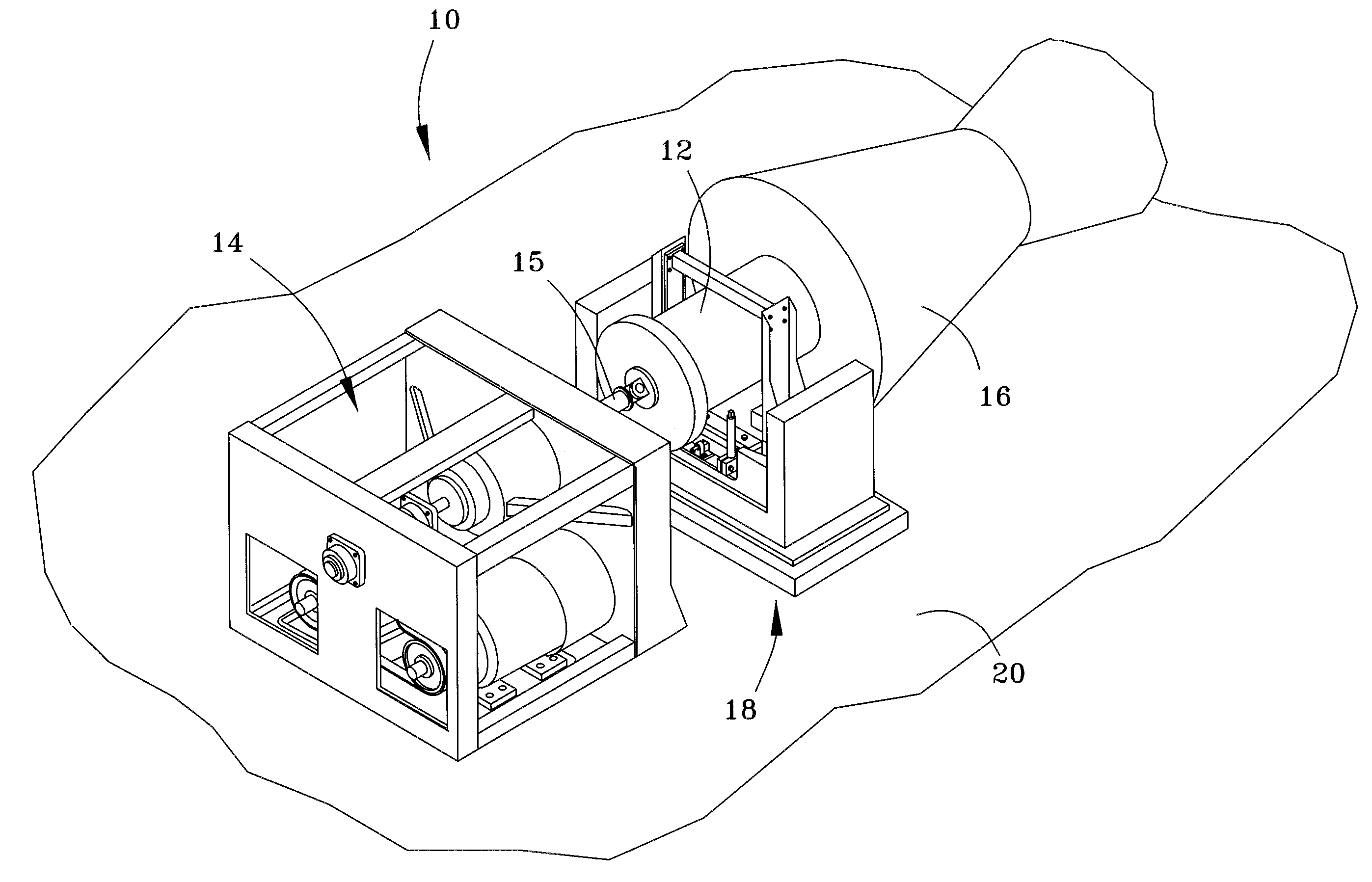
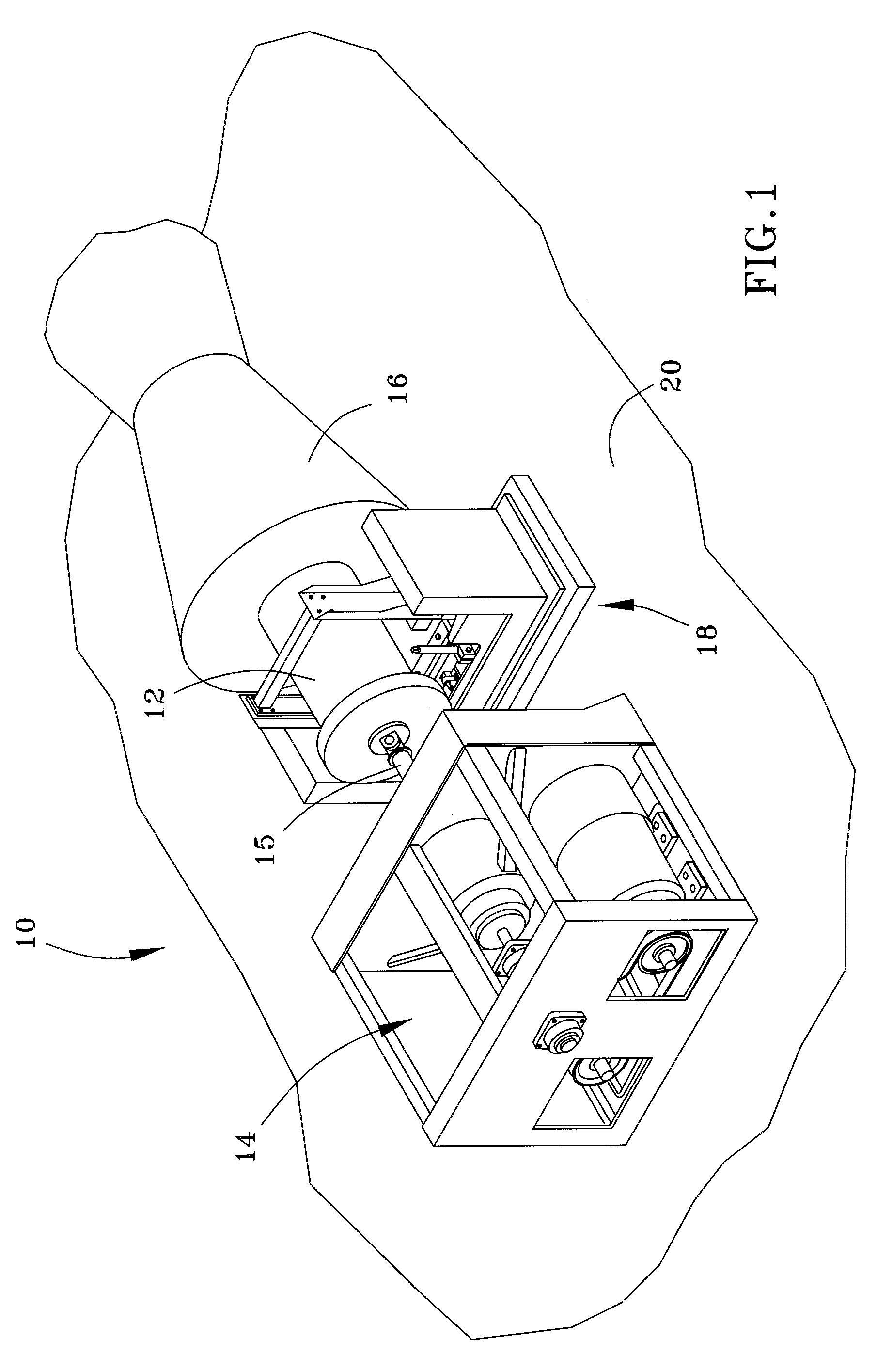
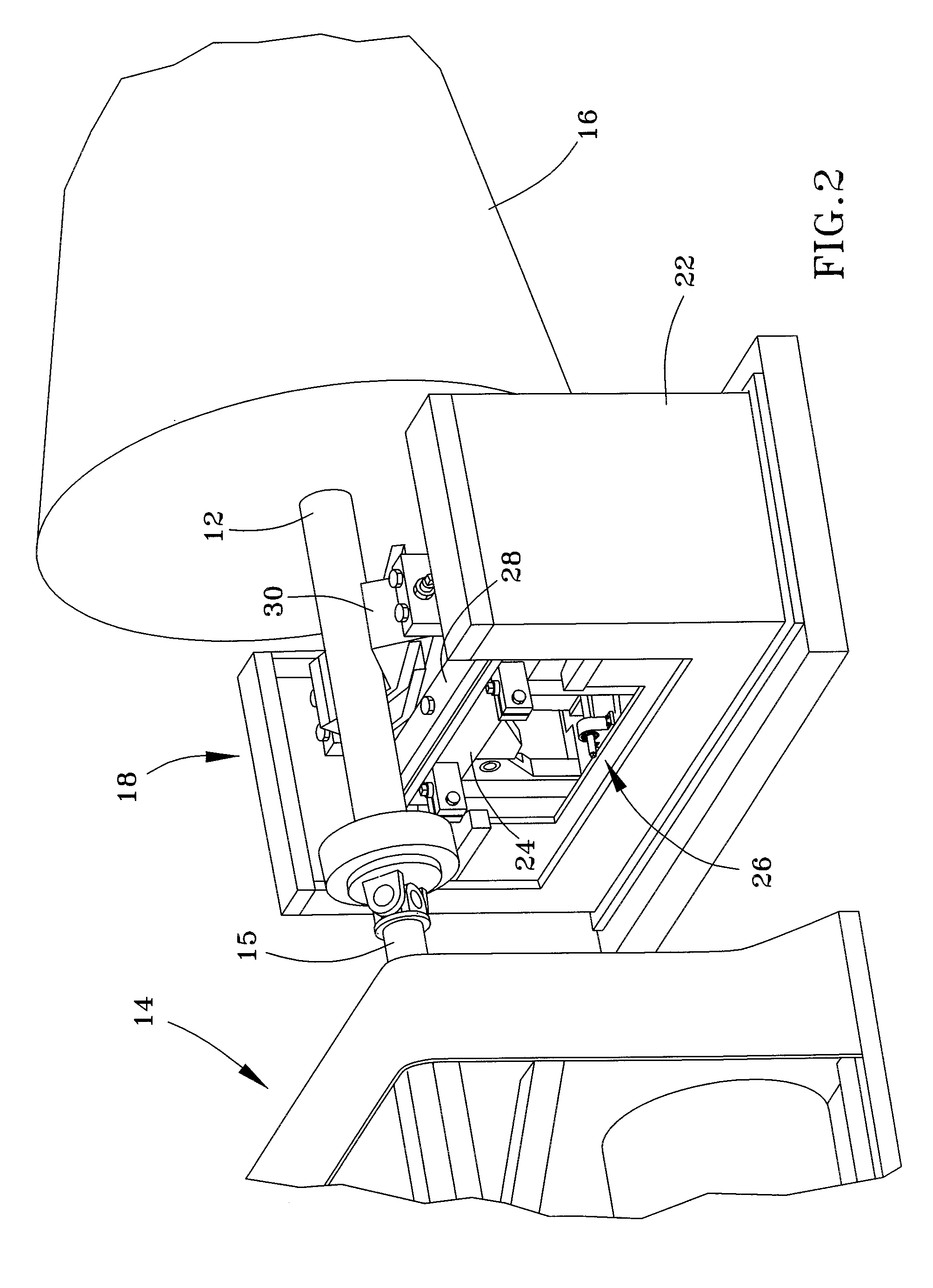
[0018]FIG. 1 represents a turbine rotor repair station 10 in accordance with an embodiment of this invention. A rotor component 12 is represented as being mounted in the station 10 for the purpose of undergoing inspection, service, or some other operation that may be desired during manufacturing or after the component 12 is returned from service. The component 12 is represented as a relatively large diameter rotor, though rotors and rotor shafts with far smaller diameters (FIGS. 2 and 8) are also within the scope of the invention. While the invention will be described in reference to rotor components, which may be rotors and shafts configured for installation in a steam turbine, gas turbine, jet engine, etc., cylindrical components other than rotors are also within the scope of this invention, including generator rotors, steel mill rolls, coal crushers, etc. Furthermore, though particularly adapted to support rotating components, from the following it will become apparent that the r...


PUM


Abstract

An apparatus and method suitable for supporting a cylindrical component. The apparatus includes a pedestal having an upper surface with a semispherical concave shape, and a carriage supported on the upper surface of the pedestal. The carriage has a lower surface and an oppositely-disposed upper surface with elements for contacting and rotatably supporting the cylindrical component. The lower surface of the carriage engages the upper surface of the pedestal and has a semispherical convex shape complementary to the semispherical concave shape of the upper surface of the pedestal. The apparatus further includes a reservoir at and recessed in the upper surface of the pedestal, and a feature for delivering a lubricant to the lubricant reservoir. The lower surface of the carriage and the upper surface of the pedestal define an enclosure around the reservoir.

Description

BACKGROUND OF THE INVENTION[0001]The present invention generally relates to equipment adapted for supporting articles. More particularly, this invention relates to a self-aligning support assembly capable of supporting a cylindrical component, and in particular large rotatable cylindrical components such as during the manufacture, inspection, and / or servicing of rotors and shafts of turbomachinery, generators, and other axisymmetric components.[0002]Depending on particular operating conditions, rotors used in steam turbines, gas turbines, and jet engines can have assembled or monolithic constructions. For example, large steam turbines typically have a bolted construction made up of separate rotors, each having a shaft with an integrally-formed wheel whose rim is configured for mounting buckets (blades). The configuration and composition of each separate rotor segment are chosen for the particular section of the turbine (for example, high pressure and low pressure stages) in which th...

Claims


Application Information

Patent Timeline
IPC IPC(8): F16M11/20F16M5/00
CPCF16C13/04F16C2360/00F16C35/00F16C32/0666
Inventor SASSATELLI, JOHN MATTHEWPOPHAM, GARY CHARLESKOLK, MICHAEL RAYMOND
Owner GENERAL ELECTRIC CO
Why Eureka
Try Eureka