Bidirectional dc-dc converter

a dc-dc converter and bi-directional technology, applied in the direction of dc-dc conversion, power conversion systems, instruments, etc., can solve the problems of complicated circuit configuration, double circuit configuration, complicated circuit configuration, etc., and achieve simple circuit configuration, increase the number of voltage error amplifier circuits, and simplify circuit configuration

Inactive Publication Date: 2010-07-01
PANASONIC CORP
View PDF3 Cites 30 Cited by
  • Summary
  • Abstract
  • Description
  • Claims
  • Application Information

AI Technical Summary

Benefits of technology

[0071]As described above, according to the bi-directional DC-DC converter of the present invention, the number of voltage error amplifier circuits is increased, but the circuit configuration can be simplified by decreasing the number of 3-terminal switches from conventional three pieces to one piece, and in addition, no inverting circuit is needed. Accordingly, it is possible to realize a bi-directional DC-DC converter having a simple circuit configuration as a whole.

Problems solved by technology

Such a bi-directional DC-DC converter can be realized just by using a pair of DC-DC converters for performing voltage step-down operation and voltage step-up operation, but it results in doubling the circuit configuration, causing it to become complicated.
In the conventional configuration using three pieces of such 3-terminal switch, the configuration can be simplified as compared with the case of using a pair of DC-DC converter for voltage step-down operation and voltage step-up operation, but there still arises a problem of complicated circuit configuration as a whole.

Method used


Image

  • Bidirectional dc-dc converter
  • Bidirectional dc-dc converter
  • Bidirectional dc-dc converter

Examples


embodiment 1

Preferred Embodiment 1

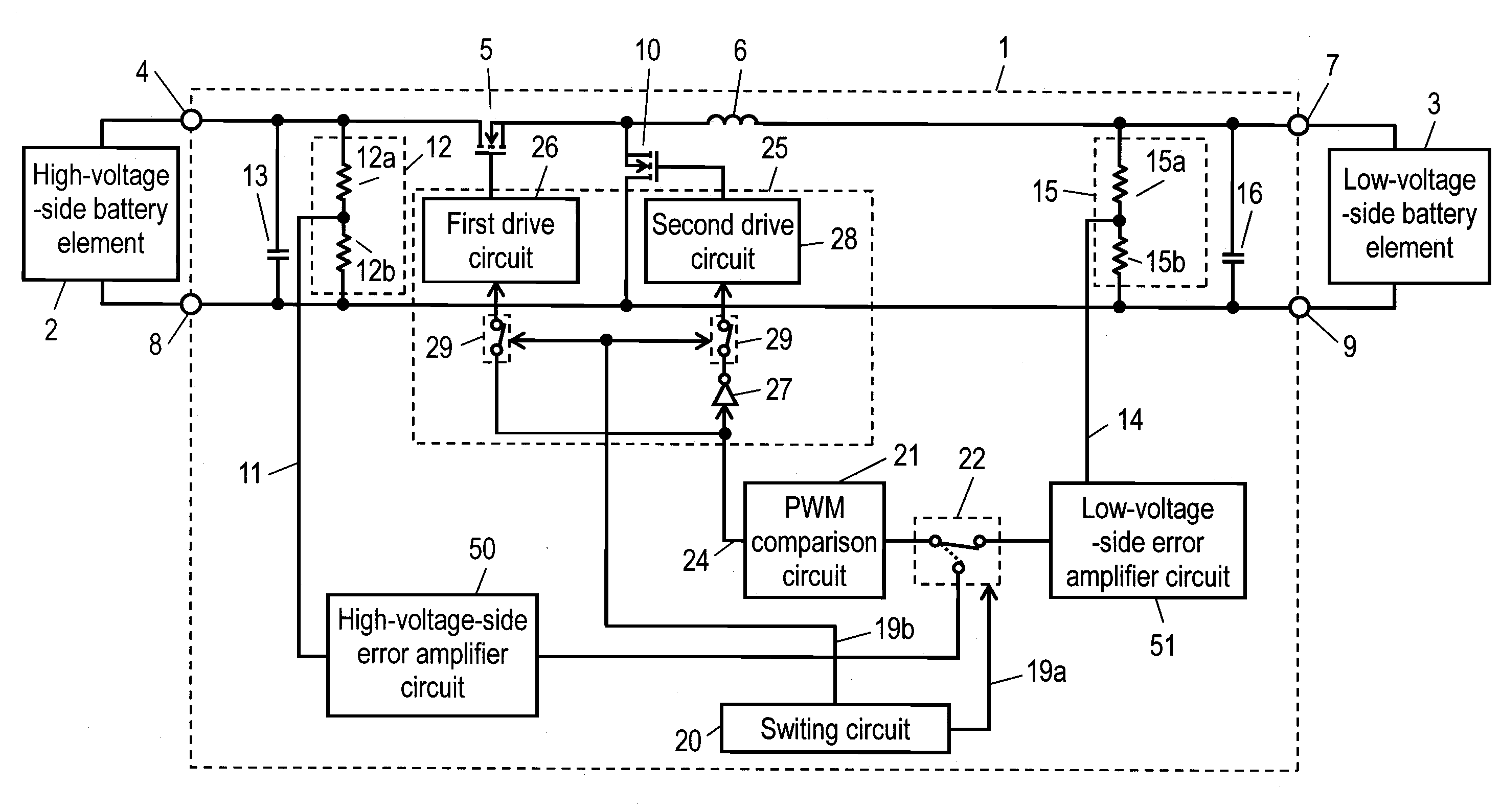
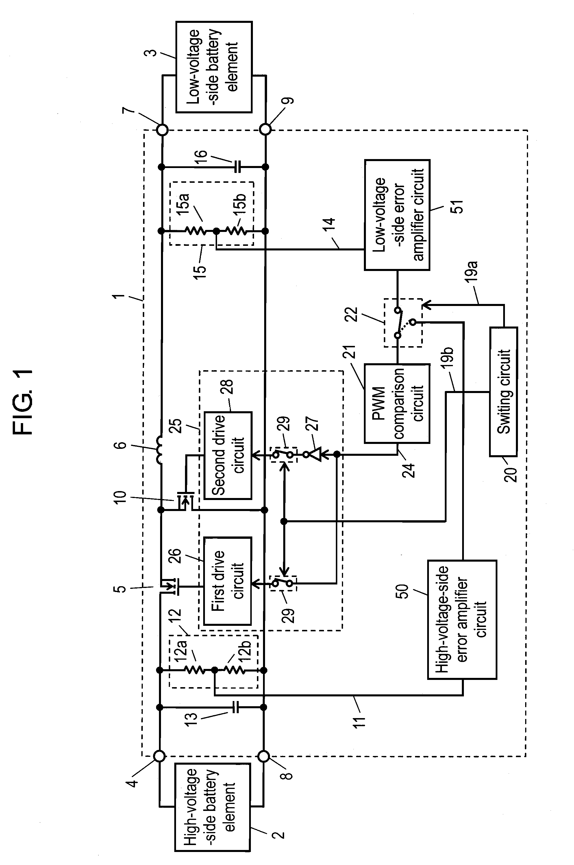
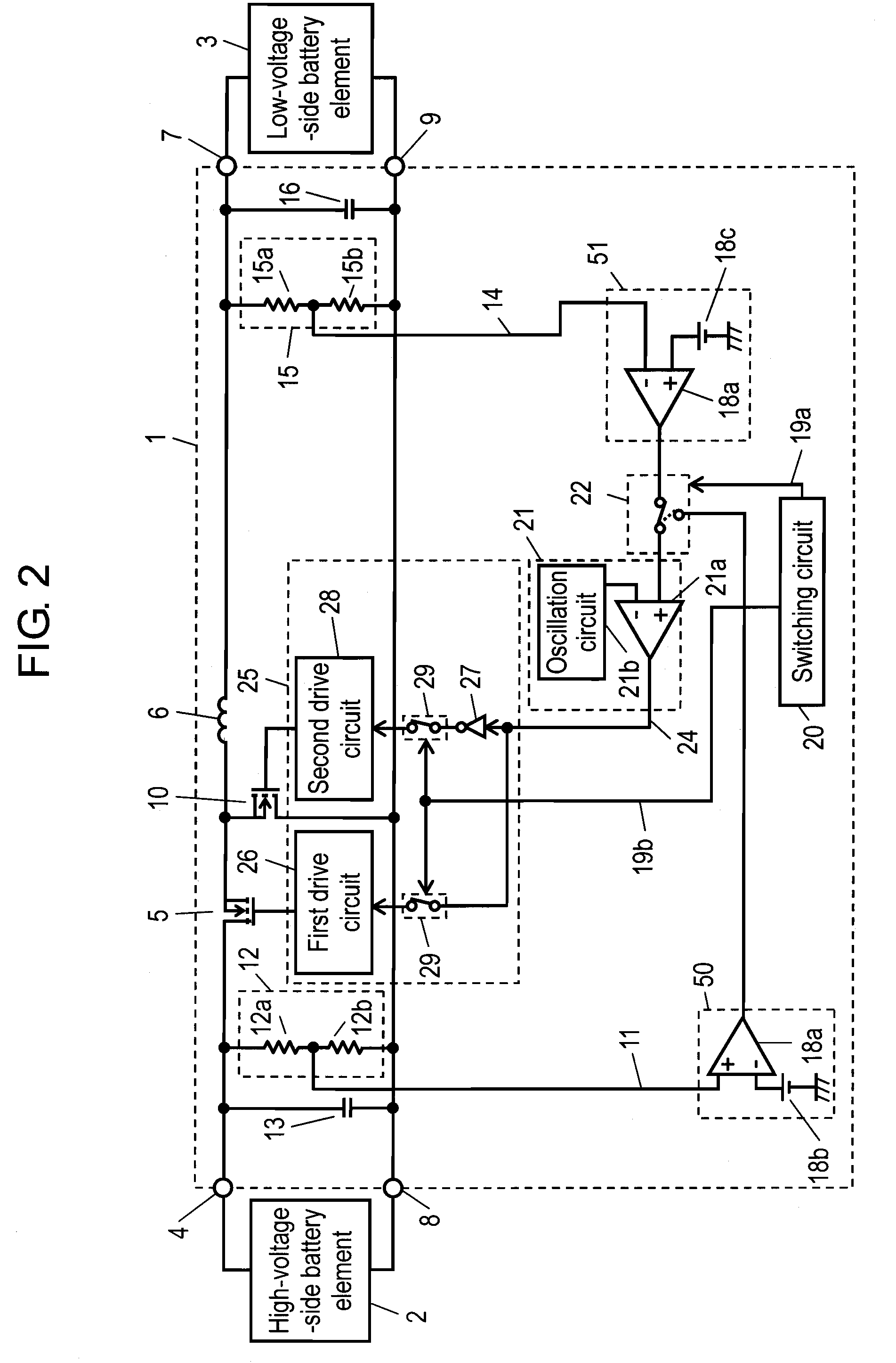
[0123]In the preferred embodiment 1, a case of constant voltage output control is disclosed. FIG. 1 is a block circuit diagram of a bi-directional DC-DC converter in the preferred embodiment 1 of the present invention. FIG. 2 is a partially detailed block circuit diagram of a bi-directional DC-DC converter in the preferred embodiment 1 of the present invention. In FIG. 1 and FIG. 2, same components as in conventional FIG. 6 and FIG. 7 are given same reference numerals, and the detailed description is omitted.

[0124]In FIG. 1, the difference in circuit configuration from the conventional example is as follows.

[0125](1) The output (high-voltage side control voltage 11) of high voltage detection circuit 12 for detecting the voltage of high-voltage side battery element 2 is inputted to high-voltage side error amplifier circuit 50. The output (low-voltage side control voltage 14) of low voltage detection circuit 15 for detecting the voltage of low-voltage side batter...

embodiment 2

Preferred Embodiment 2

[0151]In the preferred embodiment 2, a case of constant current output control is disclosed. FIG. 3 is a partially detailed block circuit diagram of a bi-directional DC-DC converter in the preferred embodiment 2 of the present invention. In FIG. 3, same components as in FIG. 2 are given same reference numerals, and the detailed description is omitted.

[0152]First, in FIG. 3, the difference in circuit configuration from FIG. 2 is as follows.

[0153](1) For the purpose of constant current output control, there are provided high-voltage side current detection circuit 52 and low-voltage side current detection circuit 53.

[0154](2) Consequently, high voltage detection circuit 12 and low voltage detection circuit 15 are eliminated.

[0155]Other circuit configuration than the above is same as in the preferred embodiment 1. Accordingly, in the case of constant current output control, 3-terminal switch 30 includes only converting direction switching circuit 22, and inverting ...

embodiment 3

Preferred Embodiment 3

[0162]In the preferred embodiment 3, a case of constant voltage output control and constant current output control concurrently is disclosed. FIG. 4 is a partially detailed block circuit diagram of a bi-directional DC-DC converter in the preferred embodiment 3 of the present invention. In FIG. 4, same components as in FIG. 2 and FIG. 3 are given same reference numerals, and the detailed description is omitted.

[0163]First, the difference in circuit configuration of FIG. 4 from FIG. 2 is shown in the following.

[0164](1) There are provided at the high-voltage side both of high voltage detection circuit 12 and high-voltage side current detection circuit 52. Similarly, there are provided at the low-voltage side both of low voltage detection circuit 15 and low-voltage side current detection circuit 53.

[0165](2) Accordingly, voltage error amplifier circuits, that is, first high-voltage side error amplifier circuit 54, second high-voltage side error amplifier circuit 5...


PUM


Abstract

The object of the present invention is to provide a bi-directional DC-DC converter having a simplified circuit configuration. Each output of high voltage detection circuit (12) and low voltage detection circuit (15) is inputted to high-voltage side error amplifier circuit (50) and low-voltage side error amplifier circuit (51) independently disposed, which are configured so as to be inverse in polarity, and the output of high-voltage side error amplifier circuit (50) or the output of low-voltage side error amplifier circuit (51) is selected by converting direction switching circuit (22), and the output is inputted to control circuit (25) from PWM comparison circuit (21) being in common with respect to voltage step-up and decreasing operations, thereby driving the first switching element (5) and the second switching element (10). Thus, a inverting circuit conventionally used is not needed, and in addition, only one 3-terminal switch usually complicated in structure is used, and it possible to realize a bi-directional DC-DC converter having a simple configuration as a whole.

Description

TECHNICAL FIELD[0001]The present invention relates to a bi-directional DC-DC converter capable of power conversion in both directions.BACKGROUND ART[0002]A DC-DC converter is an apparatus for converting a certain DC voltage to a different DC voltage, which is widely employed in various fields. The operation of a DC-DC converter includes a voltage step-down operation for converting a certain DC voltage to a lower DC voltage, and a voltage step-up operation for converting a certain DC voltage to a higher DC voltage. A bi-directional DC-DC converter which performs voltage step-down operation or voltage step-up operation for charging in both directions between two kinds of battery elements being different in voltage is also developed.[0003]Such a bi-directional DC-DC converter can be realized just by using a pair of DC-DC converters for performing voltage step-down operation and voltage step-up operation, but it results in doubling the circuit configuration, causing it to become complic...

Claims


Application Information

Patent Timeline
Patent Type & Authority Applications(United States)
IPC IPC(8): G05F1/10
CPCH02M3/156H02M3/158
Inventor MATSUO, MITSUHIROYOSHIDA, KOJIHANDA, HIROYUKI
Owner PANASONIC CORP
Why Eureka
Try Eureka