Magnetic Field Sensor For Measuring A Direction Of A Magnetic Field In A Plane

a magnetic field and sensor technology, applied in the direction of instruments, galvano-magnetic hall-effect devices, galvano-magnetic devices, etc., can solve the problem of complex mathematical calculations that must be performed

Active Publication Date: 2010-07-01
ECOLE POLYTECHNIQUE FEDERALE DE LAUSANNE (EPFL)
View PDF8 Cites 87 Cited by
  • Summary
  • Abstract
  • Description
  • Claims
  • Application Information

AI Technical Summary

Benefits of technology

[0006]The named task is solve...

Problems solved by technology

A drawback of the known techniques consists in that complex mathematical calculations have to be performed t...

Method used


Image

  • Magnetic Field Sensor For Measuring A Direction Of A Magnetic Field In A Plane
  • Magnetic Field Sensor For Measuring A Direction Of A Magnetic Field In A Plane
  • Magnetic Field Sensor For Measuring A Direction Of A Magnetic Field In A Plane

Examples


Embodiment Construction

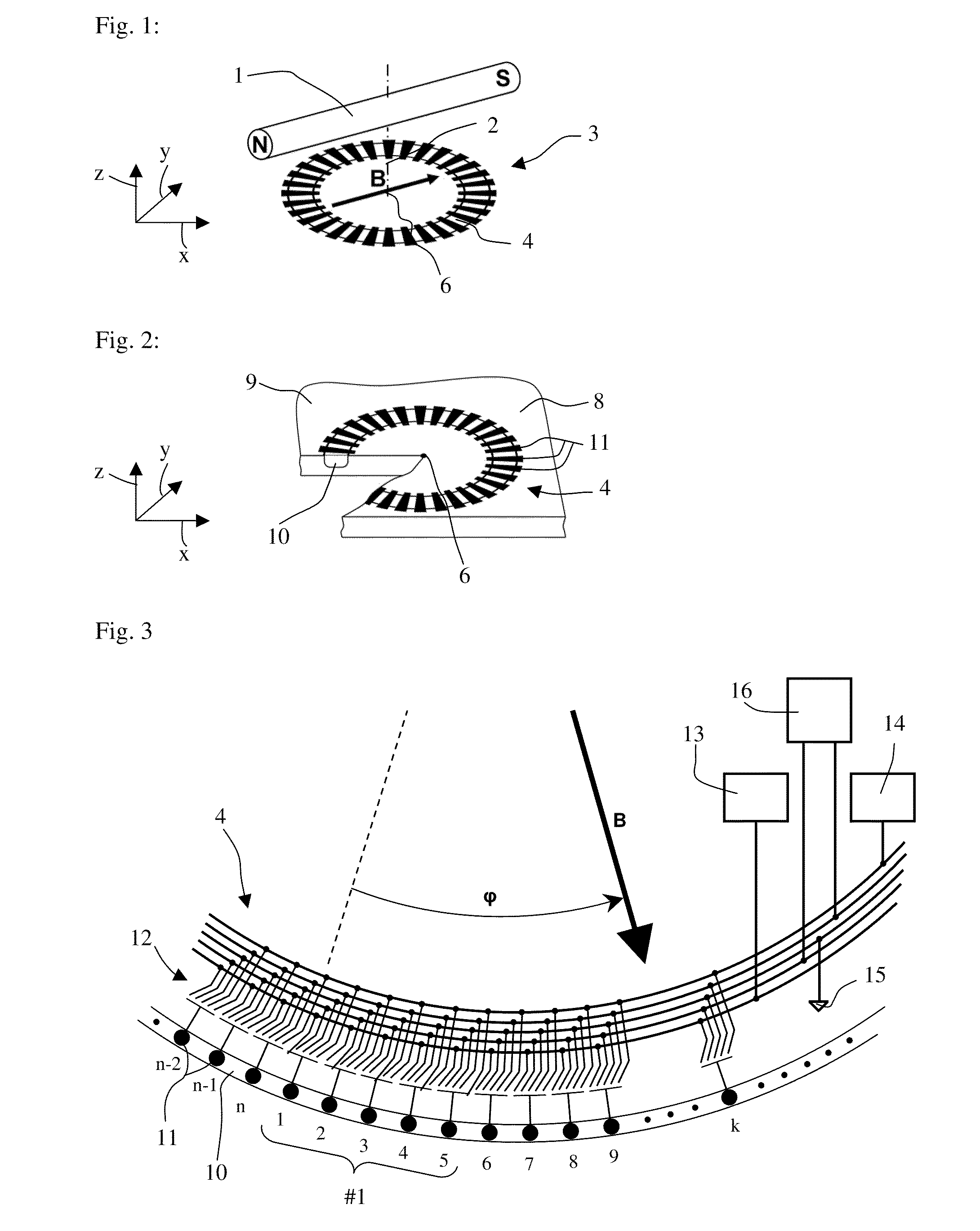
[0015]FIG. 1 shows a schematic view of the sensing principle according to the invention. The axes of a Cartesian coordinate system are designated with x, y and z. With this embodiment a permanent magnet 1 that is rotatable on a rotational axis 2 produces a magnetic field B. A sensor 3 comprising a sensing structure 4 and an electronic circuit 5 (FIG. 5) produces an output signal that represents the direction of the magnetic field B in the xy-plane. Optionally, the sensor 3 may produce a second output signal that is proportional to the strength of the magnetic field B. The sensor 3 consists of a semiconductor chip with an active surface, i.e. the sensing structure 4 and the electronic circuit 5 are embedded in the active surface. The sensing structure 4 defines the position of the x and y axes. The rotational axis 2 of the permanent magnet defines the position of the z-axis. The sensing structure 4 has a circular symmetry with a center 6. Apart from mounting tolerances the rotational...


PUM


Abstract

A magnetic field sensor for measuring a direction of a magnetic field in a plane comprises a sensing structure comprising a ring-shaped well, a plurality of contacts of equal size placed at equal distance from each other along the ring-shaped well, and an electronic circuit comprising a plurality of electronic switches associated with the contacts of the sensing structure, a logic block for controlling the electronic switches, at least one current source, a means for measuring a difference between a first voltage and a second voltage, a timing circuit providing a control signal for controlling the logic block and providing a reference signal, wherein the logic block is adapted to close and open the electronic switches under the control of the control signal according to a predetermined scheme such that a predetermined number of contacts of the plurality of contacts form a vertical Hall element that is supplied with current from the at least one current source and that has two contacts connected to the means for measuring, and such that the vertical Hall element is moved in steps along the ring-shaped well, and a means for measuring a phase shift between the reference signal and an output signal of the voltage measuring means.

Description

FIELD OF THE INVENTION[0001]The invention concerns a magnetic field sensor for measuring a direction of a magnetic field in a plane.BACKGROUND OF THE INVENTION[0002]Such a magnetic field sensor may be used in a wide range of applications, namely everywhere where the direction of a magnetic field in a plane needs to be measured. Such applications include angular position measurement in an angle encoder that contains a magnet that is rotatable on an axis, use in a compass and others.[0003]Angular position microsystems based on the magnetostatic principle mostly derive benefit from a Hall-effect sensor. They are composed of a two-dimensional sensing part combined with a rotating permanent magnet. One technique using a magnetic field concentrator is known from EP 1182461. Another technique is known from WO 9810302. Yet another technique uses a special vertical Hall sensor as described in an article available on the Internet http: / / www.novotechnik.com / pdfs / Vert-X.pdf. A drawback of the k...

Claims


Application Information

Patent Timeline
IPC IPC(8): G01R33/07
CPCG01R33/077G01R33/07
Inventor KEJIK, PAVELPOPOVIC, RADIVOJEREYMOND, SERGE
Owner ECOLE POLYTECHNIQUE FEDERALE DE LAUSANNE (EPFL)
Why Eureka
Try Eureka