High-pressure generation device

a generation device and high-pressure technology, applied in the direction of positive displacement liquid engines, pumping pumps, machines/engines, etc., can solve the problems of complex structure, high cost in most cases, and problems such as upsizing, and achieve the effects of simple structure, low cost, and relatively easy processing

Inactive Publication Date: 2010-07-01
MAGAMI MITUHARU +2
View PDF1 Cites 9 Cited by
  • Summary
  • Abstract
  • Description
  • Claims
  • Application Information

AI Technical Summary

Benefits of technology

[0023]According to the high-pressure generation device of the present invention, since all three pressure chambers are outside the pistons, a simple structure with few components is provided, and it can be mounted on a processing machine with one chuck and processed relatively easily. In addition, since the flow passage connecting the two pressure chambers is provided within the housing located outside the pistons, it is possible to downsize the device. Successive pressurization by the three pressure chambers can discharge liquid with a predetermined pressure from the beginning of operation. Furthermore, the thrust and speed of the reciprocating motion by the drive unit are made constant, thereby allowing liquid with a constant pressure to be discharged continuously at all times and this also allows liquid with a constant quantity to be discharged continuously at all times.

Problems solved by technology

Piston pumps which bring about less pulsatory motion in liquid to be discharged employ, in most cases, a method that uses a plurality of pistons and a method that uses an accumulator, both of which lead to complicated structures, issues with upsizing, and high costs in most cases.
In this pressure conversion device, however, when the hydraulic oil is pressurized by the first pressure chamber, mixed air is also required to be compressed and the need to reduce compression time to the greatest extent possible remains unsatisfied.
In addition, a flow passage for the hydraulic fluid for reciprocating the control piston of a drive unit is switched by two directional control valves in a two-stage manner, resulting in a problem in that it takes time to actually perform switching.
This technique obtains high pressure gas by compressing the gas in a three-stage manner, but there are difficulties in applying it directly to liquid because of its structure.
In addition, since it discharges only gas once for each reciprocating operation of a piston, even if it is applied to liquid, the pressure fluctuation of the liquid being discharged is large, and the demand to eliminate pulsation cannot be satisfied.
In this high-pressure generation device, however, as shown in FIG. 9, the three chambers are inside the H-shaped piston, making its structure complicated and the number of components large.
In addition, since high-precision concentricity and perpendicularity are required for the components, component processing is extremely difficult, and it is difficult to avoid processing errors caused by chucking.
Furthermore, since the flow passage communicating the first chamber and the second chamber is provided within the piston, and a backflow prevention valve is required to be provided at this position, it is difficult to downsize the piston, thereby providing an obstacle to the downsizing of the high-pressure generation device.

Method used


Image

  • High-pressure generation device
  • High-pressure generation device
  • High-pressure generation device

Examples


Embodiment Construction

[0047]Hereinafter, the high-pressure generation device of the embodiments provided in accordance with the present invention will be described with reference to the drawings.

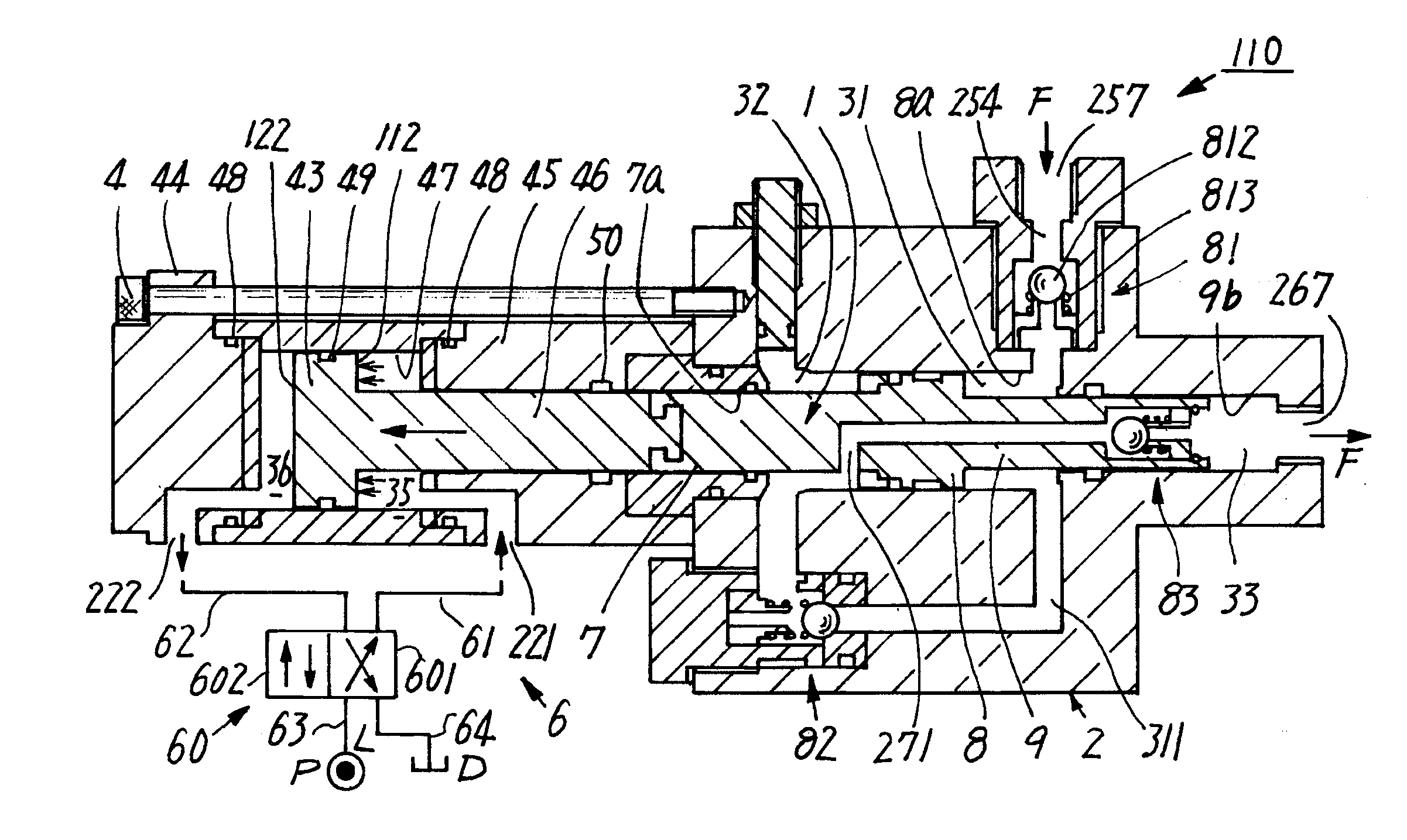
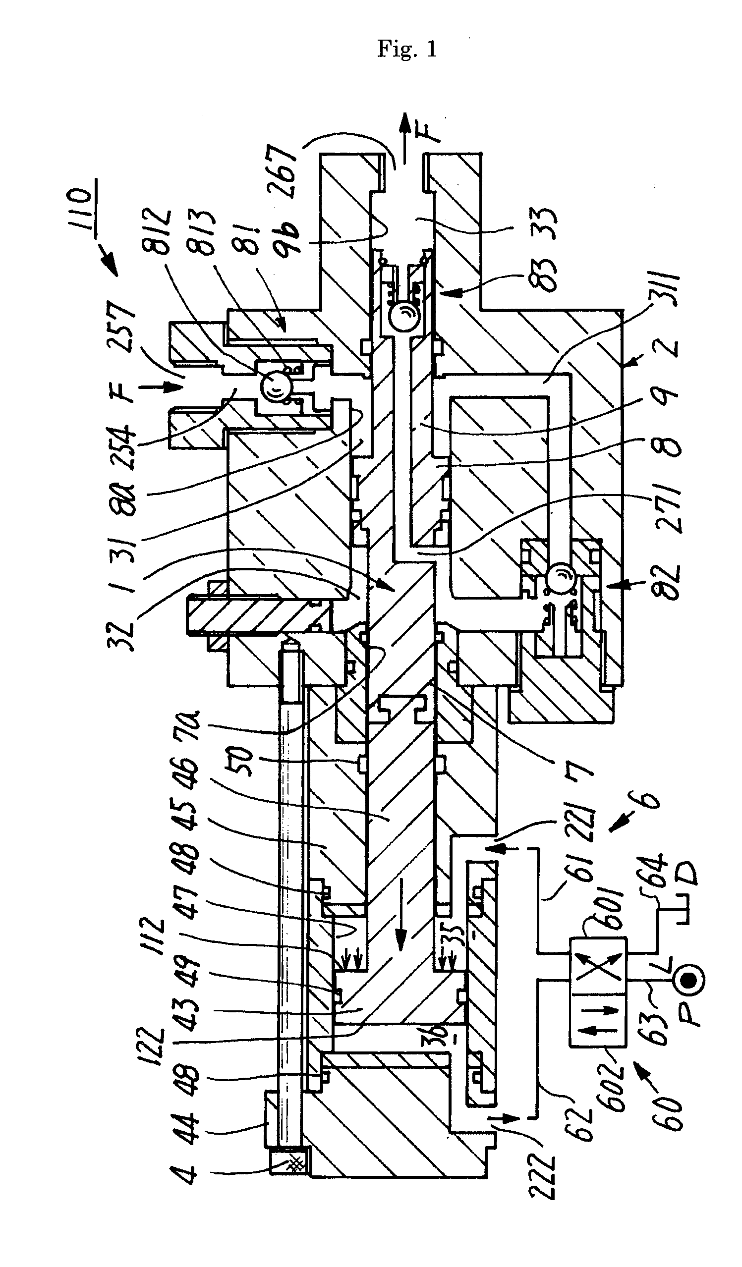
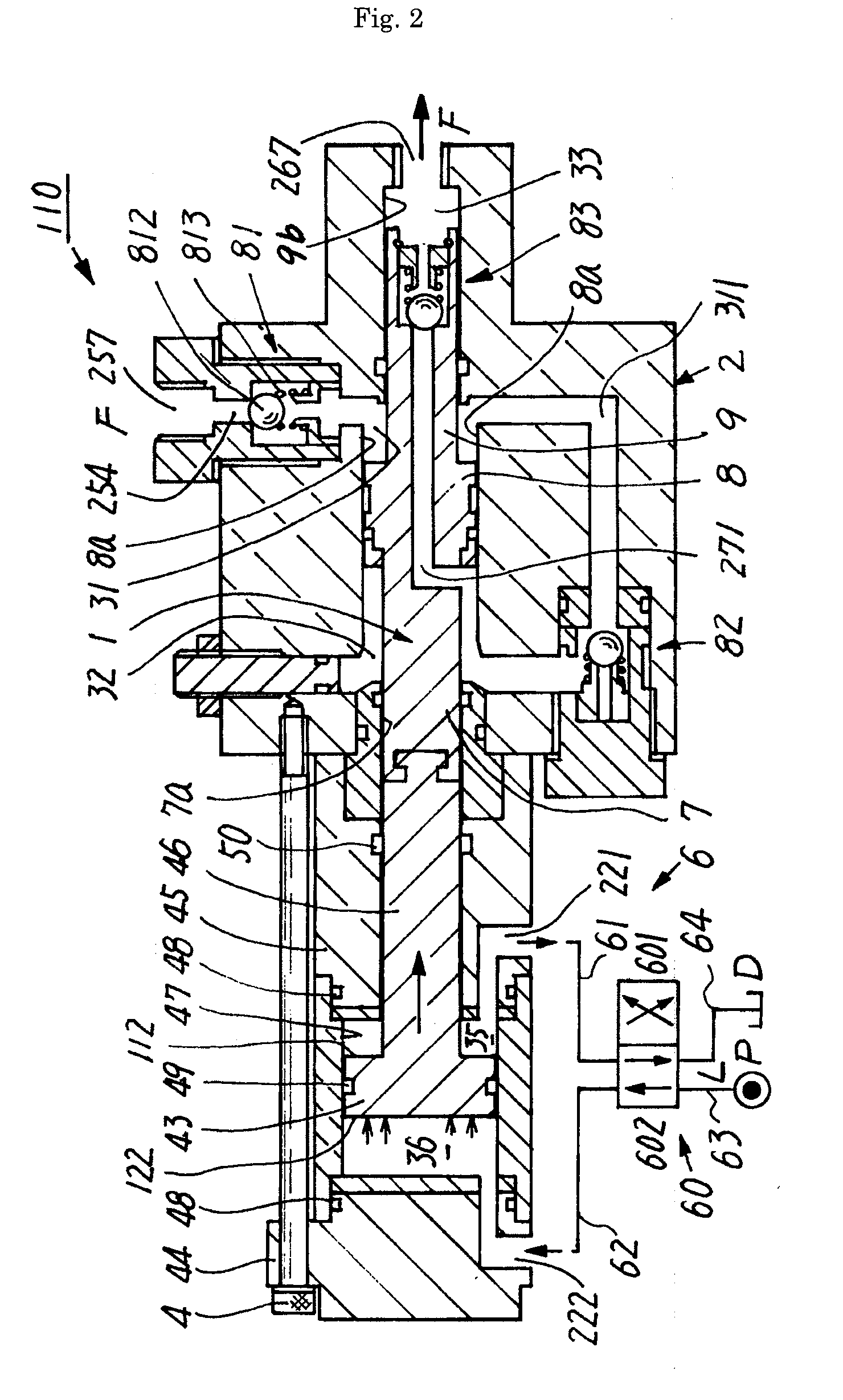
[0048]FIG. 1 and FIG. 2 are cross-sectional views showing examples of the high pressure generation device in accordance with one embodiment of the present invention.

[0049]As shown in FIG. 1 and FIG. 2, the high pressure generation device 110 in accordance with one embodiment of the present invention is provided with three pressure chambers, that is, a first pressure chamber 31, a second pressure chamber 32, and a third pressure chamber 33 for performing a pumping operation to pressurize and discharge liquid in a space in which a piston 1 fitted into a housing 2 reciprocates, an intake port 257 for drawing the liquid from the outside into the first pressure chamber 31, a first flow passage 254 for communicating the intake port 257 and the first pressure chamber 31, a second flow passage 311 for communicating the f...


PUM


Abstract

The high-pressure generation device (110) comprises three pressure chambers which pressurize liquid drawn from the outside through the pumping operation of a plurality of pistons (1) having different outer diameters, pressurizes the liquid drawn from the outside, and discharges the liquid pressurized to a constant pressure to the outside in each reciprocating operation of the plurality of pistons (1). The three pressure chambers comprising a first pressure chamber (31) which draws liquid from the outside, a second pressure chamber (32) of which the pressurizing area for pressurizing the liquid is smaller than that of the first pressure chamber (31), and a third pressure chamber (33) of which the pressurizing area is smaller than that of the second pressure chamber (32) and which discharges liquid to the outside. The pressurizing areas of the second pressure chamber (32) and the third pressure chamber (33) are set so that the ratio of the difference between the pressurizing areas of the second pressure chamber (32) and the third pressure chamber (33) to the thrust when the plurality of pistons move in the one direction is equal to the ratio of the pressurizing area of the third pressure chamber (33) to the thrust when the plurality of pistons move in the other direction.

Description

FIELD OF THE INVENTION[0001]The present invention relates to a high-pressure generation device which draws in fluid and discharges it at high pressure.BACKGROUND OF THE INVENTION[0002]A piston pump (also referred to as a “plunger pump”) has been used to discharge pressurized liquid at high pressure. The piston pump reciprocates a liquid drawing / compressing piston using an external power source, compresses the liquid drawn in from the outside, and discharges the pressurized liquid at high pressure. Various types of drive units for reciprocating the drawing / compressing piston are available, such as one which converts the rotary motion of a motor or engine as the power source into a reciprocal motion and one which reciprocates a control piston by feeding pressurized fluid as the power source into a fluid pressure cylinder (See Japanese Patent No. 3297143).[0003]In order to discharge liquid at high pressure, a piston pump is required to discharge fluid which has been subject to draw / com...

Claims


Application Information

Patent Timeline
Patent Type & Authority Applications(United States)
IPC IPC(8): F04B5/02F04B3/00
CPCF04B3/00F04B5/02F04B9/113
Inventor MAGAMI, MITUHARUMAGAMI, NAOYUKIMAGAMI, TAKUYA
Owner MAGAMI MITUHARU
Why Eureka
Try Eureka