[0034]Another
advantage of the present invention is that the need to perform
signal summation and scaling to derive the downmix signal at each TTO or TTT encoding block is eliminated, again reducing the computational requirement. These signal operations are represented by summation and scaling of the input channel-coefficients pair or triplet. While for simplicity the present description refers to input channel-coefficients, one skilled in the relevant art will recognize that an input channel-coefficient is a type of coincident-to-surround channel coefficient and that the present invention is equally applicable to any coincident-to-surround channel coefficient. In the present example, instead of the actual surround channel signals, only their respective channel coefficients are navigated through the encoding tree. Again, this is possible because signal downmixing and scaling are linear operations. The last encoding block outputs the dowmnix channel-coefficients matrix that is used to derive the output-downmix signals from the
microphone array signals.
[0035]For a stereo-based encoding configuration, one embodiment of the present invention provides an
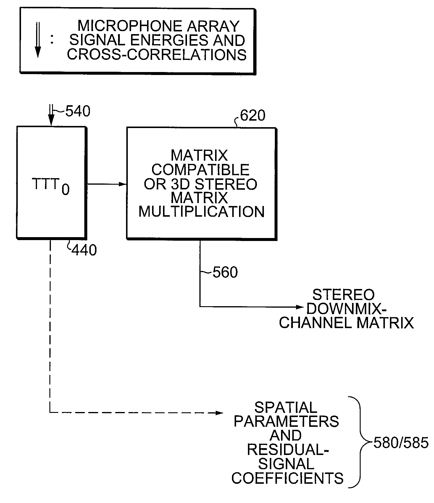
advantage in terms of the derivation of matrix-compatible or 3D-stereo downmix. The post-
processing required to derive downmixes can, according to the present invention, be implemented efficiently by integrating the 2×2 conversion matrix into the stereo-downmix channel-coefficients matrix, practically adding no significant computational requirement.
[0036]The computational efficiency of the present invention, as compared to the MPEG Surround encoding schemes known in the prior art, is obvious and is clearly evident as shown in the following example. Assuming that the complexity of each
hybrid analysis filtering is f (in terms of the total number of operations), the encoding scheme of the present invention requires (N−M)·F less operations where N and M are the number of the surround sound channels and coincident microphone array signals, respectively. For a conventional 5.1 surround sound (6 surround channels) with a 3-channel B-format coincident recording, this improvement amounts to a complexity savings of 50% for the
hybrid analysis filtering alone. On the
spatial parameter calculation and signal downmixing for mono-based encoding, the complexity of the generic
encoder is estimated to be (40e) multiplications and (40e) additions, where e is the total number of time-frequency points. The complexity of the encoding scheme associated with embodiments of the present invention is estimated to be (19e) multiplications and (17e) additions. Therefore, there is at least a 50% savings on the encoding scheme of the present invention as compared to the generic encoding scheme of the prior art. This saving is significant considering that each encoding frame consists of 71-by-32 time-frequency points.
[0037]FIG. 5 shows the diagram of the proposed MPS encoding scheme according to one embodiment of the present invention. For this example, assume commonly used three-channel coincident microphone techniques. For simplicity of signal labeling, B-format signals (W, X and Y) are used. However, as will be recognized by one skilled in the relevant art, the invention is applicable to any coincident surround sound recording techniques with any number of microphone signals that utilize coincident-to-virtual microphone matrixing and is not limited by the B-format signals.
[0038]In the present example, at each frame,
hybrid analysis filtering 510 is performed on the B-format signals 520.
Signal energy of W, X and Y 520 and cross-correlations between the possible signal pairs W-X, W-Y and X-Y are calculated 530 at a maximum of 28 parameter bands. This set of parameter-band signal energies and cross-correlations form a common input 540 to all TTO and TTT encoding blocks. In this depiction the TTO and TTT encoding blocks are generalized as
spatial encoding 550. (additional details are shown in FIGS. 6a and 6b) From the
spatial encoding a downmix-channel matrix 560 is formed which is combined with T / F channel signals to generate downmix signals 570. Thereafter the downmix signals are synthesized back to the
time domain 330 thus producing a downmix output. The
spatial encoding tree 550 also produces spatial parameters 580 that is
bitstream formatted 590 producing a
spatial parameter bitstream. An additional result of the spatial encoding 550 are residual-signal coefficients. These coefficients are combined with signals produced by the T / F filtering 510 to generate 565 residual signals 585. These residual signals 585 are combined with spatial parameters 580 and formatted into a bit
stream 580
[0039]FIG. 6(a) illustrates the spatial encoding stage of a scheme for stereo-based encoding configuration according to one embodiment of the present invention. While the discussion that follows confers information about the encoding process from a functional point of view, one skilled in the art will recognize that each of the blocks depicted can represent specific modules, engines or devices configured to carry out the methodology described. Accordingly the block diagrams as shown are at a high level and not meant to limit the invention in any manner. Indeed the invention is only limited by claims defined at the end of this document. As opposed to the
tree structure shown in FIG. 4(b), the actual input surround-sound channels 640 are represented by their respective channel coefficients. The same representation applies to any other encoding tree configuration, as the present invention can be implemented in several different configurations.


