Synchronizing circuit

a synchronizing circuit and circuit technology, applied in the direction of generating/distributing signals, digital transmission, instruments, etc., can solve problems such as unintended data updating, circuit scale or power consumption, and increase of the circuit on the receiving sid

Inactive Publication Date: 2010-07-01
KK TOSHIBA
View PDF5 Cites 34 Cited by
  • Summary
  • Abstract
  • Description
  • Claims
  • Application Information

AI Technical Summary

Benefits of technology

[0016]According to one aspect of the present invention there can be provided a synchronizing circuit having a power-supply-interruptible circuit section that can be subjected to a power supply interruption; a power supply interruption control circuit section configured to control the power supply interruption; and a gate circuit configured to output an output of the power-supply-interruptible circuit section as a fixed value when the power-supply-interruptible circuit section has been subjected to a power supply interruption; wherein: the power-supply-interruptible circuit section has a first data transmission register configured to output data for controlling the power supply interruption, and a clock enable control register configured to output a clock enable signal for performing control of a clock signal; and the power supply interruption control circuit section has a gated clock buffer configured to perform control of the clock signal based on the clock enable signal, and a first data reception register configured to take in the data that is output from the first data transmission register based on the clock signal that is controlled by the gated clock buffer.

Problems solved by technology

With an asynchronous data path that straddles a boundary surface of an internal partial power supply interruption circuit, a problem may arise with regard to the circuit scale or power consumption that does not occur with an ordinary asynchronous data path.
Accordingly, there has been the problem that, with respect to the internal partial power supply interruption control circuit section, unintended updating of data is performed at the control register by the fixed value of “0” or “1”.
However, according to the synchronizing circuit described in Non-Patent Document 1, there is the problem that the scale of the circuit on the receiving side increases.
When this method is applied to a circuit for which it is desired to reduce an operating power such as an internal partial power supply interruption circuit section, there is the problem that since the circuit scale increases, a standby electric current increases.
Thus, conventionally, on an asynchronous data path from an internal partial power supply interruption circuit to an internal partial power supply interruption control circuit, there has been the problem that a control value can be rewritten by a fixed value of an isolation cell.
Further, since the circuit scale of an internal partial power supply interruption control circuit increases when a synchronizing design is adopted for an asynchronous data path, there has been the problem that a standby electric current increases.

Method used


Image

  • Synchronizing circuit
  • Synchronizing circuit
  • Synchronizing circuit

Examples


first embodiment

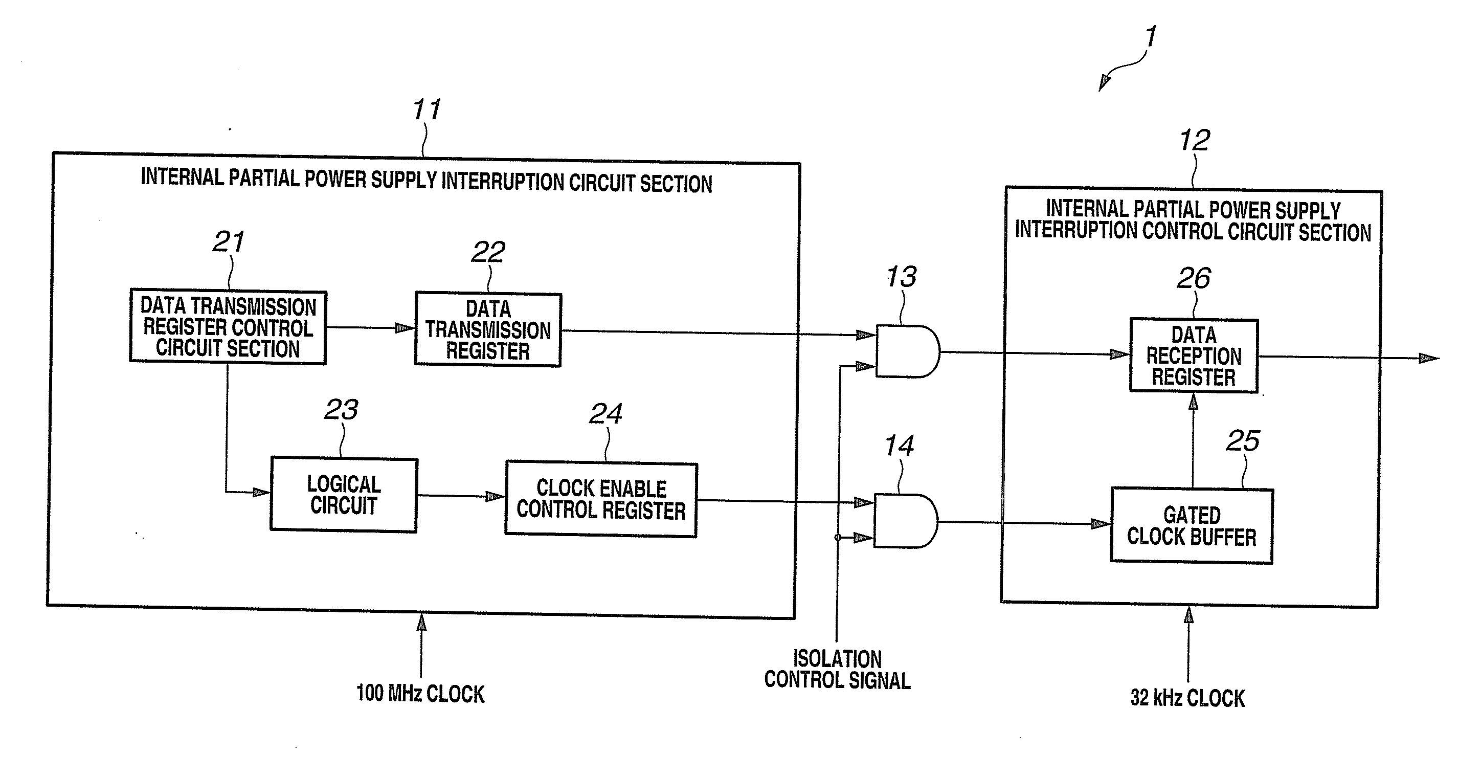
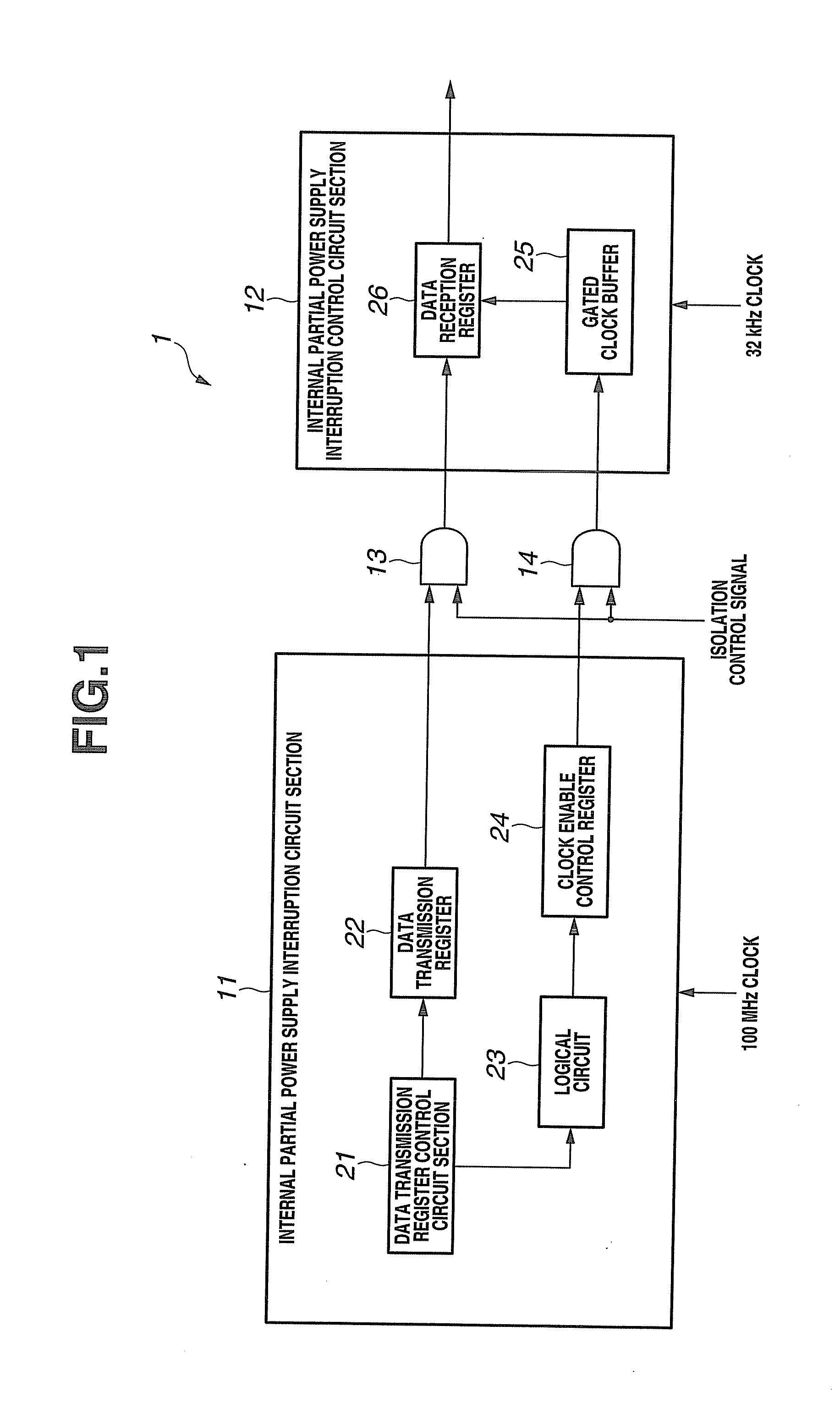
[0031]First, the configuration of a synchronizing circuit according to a first embodiment of the present invention is described based on FIG. 1. FIG. 1 is a block diagram that shows the configuration of a synchronizing circuit according to the first embodiment of the present invention. As shown in FIG. 1, a synchronizing circuit 1 includes an internal partial power supply interruption circuit section 11 that is driven with a fast frequency such as 100 MHz, an internal partial power supply interruption control circuit section 12 that is driven with a slow frequency such as 32 kHz, and AND-type isolation cells 13 and 14 that are inserted in a signal wire between the internal partial power supply interruption circuit section 11 and the internal partial power supply interruption control circuit section 12.

[0032]The internal partial power supply interruption circuit section 11 is a power-supply-interruptible circuit section with power-gating circuit configured such that a power supply th...

second embodiment

[0075]Next, a second embodiment will be described. FIG. 10 is a block diagram that shows a configuration of a synchronizing circuit according to the second embodiment of the present invention. In this connection, components in FIG. 10 that are the same as those in FIG. 4 are denoted by the same reference numbers, and a description of those components is omitted hereunder.

[0076]According to the first embodiment, synchronizing of an asynchronous data path from the internal partial power supply interruption circuit section 11 to the internal partial power supply interruption control circuit section 12 was described. However, according to the present embodiment, synchronizing of an asynchronous data path from the internal partial power supply interruption control circuit section 12 to the internal partial power supply interruption circuit section 11 will be described.

[0077]As shown in FIG. 10, in addition to the components of the synchronizing circuit 1 of the first embodiment, a synchr...

third embodiment

[0085]Next, a third embodiment is described. FIG. 13 is a block diagram that illustrates the configuration of a synchronizing circuit according to the third embodiment of the present invention. In this connection, components in FIG. 13 that are the same as those in FIG. 10 are denoted by the same reference numbers, and a description of those components is omitted hereunder. A synchronizing circuit 1b of the third embodiment is a synchronizing circuit that ensures bidirectional asynchronous data transfers between the internal partial power supply interruption circuit section 11 and the internal partial power supply interruption control circuit section 12.

[0086]As shown in FIG. 13, the synchronizing circuit 1b of the present embodiment is configured using a data transmission register control circuit section 21b instead of the data transmission register control circuit section 21a of the synchronizing circuit 1a of the second embodiment. Further, the synchronizing circuit 1b of the thi...


PUM


Abstract

A synchronizing circuit includes an internal partial power supply interruption circuit section which can be subjected to a power supply interruption and includes a data transmission register configured to output data for controlling a power supply interruption and a clock enable control register configured to output an enable signal; an internal partial power supply interruption control circuit section configured to control a power supply interruption and includes a gated clock buffer configured to control a clock signal based on the enable signal, and a data reception register configured to take in data based on the controlled clock signal; and an isolation cell configured to output an output from the internal partial power supply interruption circuit section as a fixed value when the internal partial power supply interruption circuit section has been subjected to a power supply interruption.

Description

CROSS-REFERENCE TO RELATED APPLICATION[0001]This application is based upon and claims the benefit of priority from the prior Japanese Patent Application No. 2008-330837 filed in Japan on Dec. 25, 2008, the entire contents of which are incorporated herein by reference.BACKGROUND OF THE INVENTION[0002]1. Field of the Invention[0003]The present invention relates to a synchronizing circuit, and more particularly to a synchronizing circuit that can carry out reduced power consumption at a time of a power supply interruption.[0004]2. Description of the Related Art[0005]In recent years, increases in the scale and functionality of LSIs are proceeding accompanying the development of semiconductors. On the other hand, reductions in standby power are being sought for portable devices and sensor networks and the like. In a high function LSI, all of the functions are not in constant operation, and reduced power consumption can be realized by stopping the operations of circuit sections that are n...

Claims


Application Information

Patent Timeline
Patent Type & Authority Applications(United States)
IPC IPC(8): G06F1/30G06F1/12
CPCG06F1/10Y02D10/128G06F1/3237G06F1/3203Y02D10/00
Inventor KAJIHARA, HIROTSUGU
Owner KK TOSHIBA
Why Eureka
Try Eureka